
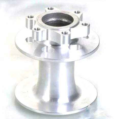
A check valve body has one moving part, and its entire life is in the gap between it and the seat
A brass or stainless steel check valve body is a machined body that contains a poppet, a ball, a disc, or a flap, and a seat that it closes against. That is a simple description of a part whose function depends on a very small clearance, on a surface finish, and on a flow behaviour that the geometry controls. The body is not a fitting that happens to have a valve in it. It is a valve body, and every dimension on it is either a flow dimension or a sealing dimension.
We machine these with turning, milling and drilling in as few setups as the geometry allows, and first articles verify the whole flow before the run is released, on CNC turning centres with bar feeders and 3- and 4-axis machining centres, backed by CNC turning centres and a climate-controlled inspection room. General tolerance is +/-0.02 mm with tighter bands on flagged dimensions, and finer bands confirmed from capability data before quoting. Standard stock is carbon steel in SPCC and DC01 grades, 304 and 316 stainless steel, aluminium and brass, with the final grade fixed at the drawing review. Surface treatment is matched to the duty – plating, coating or polishing – with the agreed finish travelling with the part number. This page is about the seat, the clearance, and the four things that decide whether a check valve body works.
The seat, which is the most important surface on the part
Everything about a check valve body’s quality comes down to the seat, and a seat is four specifications rather than one:
- Geometry. A flat seat, a conical seat, a spherical seat, or a knife-edge seat – and each behaves differently. A flat seat is simple and tolerant of misalignment; a conical seat gives a good seal under pressure and needs concentricity; a spherical seat mates with a ball and needs a defined radius and good surface finish; a knife-edge is used on very low-pressure or high-cycle applications where the lowest cracking pressure matters more than tightness.
- Size. The seat’s diameter sets the flow area and – on a low-pressure valve – the cracking pressure. This is a functional dimension, and a general machining band is not adequate for it.
- Surface finish. A seat that seals against a soft poppet needs a fine, consistent finish so the seal is repeatable. A seat that seals against a metal poppet can tolerate more. This has to be matched to the poppet material, which means the poppet is part of the seat’s specification.
- Concentricity and perpendicularity to the flow path. A seat that is not square to the body’s axis will not seal evenly around its circumference, and on a poppet that is guided by the body this produces a wear pattern and a leak. This is a tight-band geometric requirement and it is the reason a check valve body is machined rather than drawn.
Cracking pressure, and why it is a tolerance on a machined feature
A check valve has to open when the line pressure exceeds the downstream pressure by a small margin, and that margin – the cracking pressure – is a design number. It is set by:
- The poppet’s mass and the spring’s force, for a spring-loaded design. The lighter the poppet and the softer the spring, the lower the cracking pressure.
- The seat’s contact area. A larger seat area needs more pressure to open, because more area is being unseated. So the seat’s diameter is a cracking-pressure parameter and not only a flow parameter.
- The guide’s clearance. Where the poppet is guided in the body, a loose guide lets the poppet sit cocked and the cracking pressure rises or becomes erratic. So the guide bore is a functional dimension and it has to be a fit rather than a clearance.
- On a flap or swing check, the hinge’s friction and the flap’s weight set it, and a long, light flap opens at a very low pressure and chatters.
So cracking pressure is a property of the assembly, and the body’s contribution to it – seat area, guide fit, guide length – is a set of tight-band dimensions. A drawing that specifies the seat’s diameter at a general tolerance will produce valves whose cracking pressure varies across the batch, and on a check valve that variation is a functional problem rather than a dimensional one.
Flow, and the trade the seat’s diameter forces
A check valve restricts flow, and the restriction is where the design is won or lost. The relationship is direct and it is a genuine engineering trade:
- A larger seat passes more flow at a given pressure drop, and it is also easier to manufacture accurately. This is the normal answer for a general-purpose valve.
- A smaller seat lowers the cracking pressure, because less area has to be unseated. Where a valve must open at very low differential pressure – in a fuel line, in a cooling system, in a low-pressure fluid – a small seat is required, and it is harder to make consistently.
- A small seat is more prone to damage, and a small burr or a small deformation on a small seat raises the cracking pressure or stops the valve opening. So a low-cracking-pressure valve is a valve that is sensitive to cleanliness in manufacture and to debris in service.
And the classic failure mode: a low-cracking-pressure valve with a small seat, carrying a dirty fluid, chatters. The poppet opens, closes, opens, and the repeated impact on the seat eventually damages it. Where a valve sees a dirty or particulate-laden fluid, a slightly higher cracking pressure and a larger seat is the more durable design even though it is the less sensitive one.
Guides, stops and the small features that are easy to omit
A check valve body has three small features that a drawing often leaves to the shop, and each of them has a function:
- The poppet guide. A bore or a pair of lands that keep the poppet aligned. Its diameter is a fit, its length sets the poppet’s travel, and its position relative to the seat sets the poppet’s seating behaviour. A guide that is too long can stop the poppet from sealing; too short and the poppet tilts.
- The travel stop. A limit on how far the poppet can open, usually a shoulder. It sets the maximum flow area, and it also often forms part of the poppet’s sealing surface – which means a stop and a seat in one feature has to be designed as a seal, not as a bumper.
- The retention feature. How the poppet is kept in the body – a circlip groove, a snap ring, a threaded retainer, a simple press fit. This determines whether the valve is serviceable, and a valve designed for service has a groove with its own tolerance because a circlip groove’s size determines whether the clip fits and whether it retains.
A valve body’s alloy follows the medium and the pressure class
Standard stock is carbon steel in SPCC and DC01 grades, 304 and 316 stainless steel, aluminium and brass, with the final grade fixed at the drawing review. On a valve body the choice follows the medium and the pressure class:
- Brass is the standard for low-to-medium pressure water, air, fuel and general service, and it is the right answer for most check valves. It machines well – which matters because the seat and the guide are machined – it has good corrosion resistance in ordinary water and in many fuels and oils, and it is available in free-machining grades that make the machining economical. Its limits are dezincification in acidic or ammonia-bearing media, and its strength at high temperature.
- 304 stainless steel for higher pressures, higher temperatures, and more aggressive media. 316 where chlorides are present.
- 316 stainless steel for chloride-bearing, saline, and process applications, and for anything where brass would be at risk.
- Carbon steel where the medium is not corrosive and cost is dominant – typically on fuel, oil, and hydraulic lines in equipment that is not exposed to water.
- Aluminium is a poor choice for a valve body in most cases, because it has poor galling behaviour against a steel poppet, it creeps under sustained seating load, and it will not hold a fine seat surface. It is used where mass is dominant and the valve is a low-duty check.
On a valve body, mask the seat and keep it functional
Surface treatment is matched to the duty – plating, coating or polishing – with the agreed finish travelling with the part number. On a valve body the finishing requirements are strictly functional:
- Mask the seat, absolutely. A plated or coated seat changes its diameter, its hardness, and its surface – and a hard plated seat against a soft poppet will not seal and will wear. This is the most important masking requirement on the part and it should be named explicitly on the drawing rather than assumed.
- Mask the guide bore for the same reason: a plated guide changes the fit and the poppet’s alignment.
- Mask any thread, and the poppet retention feature if its size matters.
- Passivation on stainless steel is the natural choice because it changes no dimension and gives full corrosion resistance, which is exactly what a valve body needs. Plating is used where the body is visible or where a specific external surface is required.
- On a visible valve, a polished or plated body is an appearance requirement and should be assessed separately from the internal requirements – the two lead to different specifications and the internal one should not be relaxed for the external one.
Body and poppet are a matched pair
Eight things, and the first four are what turn a machined body into a valve body:
- Seat type, dimensions, surface finish, and its concentricity and perpendicularity to the body’s axis – at a tight band, and identified as the part’s primary sealing feature.
- Cracking pressure, or the flow requirement it derives from, so the seat’s area and the guide’s fit can be designed rather than guessed.
- Poppet specification, or at least its material and dimensions, because the seat’s finish and the guide’s clearance are both functions of the poppet.
- Guide bore as a fit, and the travel stop, with the stop identified if it forms part of the sealing surface.
- Flow requirement, as a pressure drop at a flow rate, which is what actually sizes the seat and the passages.
- General machining at +/-0.02 mm, with the flagged dimensions identified, and finer bands confirmed from capability data before quoting.
- Material grade, tied to the medium, and the pressure and temperature class.
- Which surfaces are masked, with the seat named explicitly.
Is the poppet supplied with this body?
Direct answer: On a check valve, the body and the poppet are a matched pair – the seat’s finish, the guide’s clearance, and the cracking pressure all depend on the poppet – and a body quoted without knowing the poppet is a body quoted with three of its four functional requirements undefined. It is worth asking, because a valve where both are supplied can be designed and tested as an assembly, while a body-only supply has to be specified generously enough to work with a poppet the customer has not yet chosen – and that generosity costs money in tolerances. The second question worth asking is the flow direction and the medium, because on a check valve the direction is not a detail and the medium decides whether the seat material is right.
What sets a check valve’s cracking pressure?
Direct answer: It is a tolerance on a machined feature rather than a spring-only number. The cracking pressure – the small margin by which line pressure must exceed downstream pressure to open the valve – is set by the poppet’s mass and the spring’s force, by the seat’s contact area, and by the guide’s fit. A larger seat area needs more pressure to open and is easier to machine accurately; a smaller seat lowers the cracking pressure because less area has to unseat. The seat’s dimensions are therefore the cracking pressure in machined form.
Which alloy should a check valve body use?
Direct answer: The choice follows the medium and the pressure class. Brass is the standard for low-to-medium pressure water, air, fuel and general service, and it is the right answer for most check valves because it machines well and resists most of what a check valve sees. Stainless steel – 304 or 316 – takes over where the medium is corrosive or the pressure class is higher. The grade is fixed at the drawing review rather than assumed.
This part belongs to our CNC Machining Parts range. The cnc machining parts pages collect the process notes, common materials and inspection points behind every product in the family.
Specifications
| Item | Brass and Stainless Steel Check Valve Bodies |
|---|---|
| Brand | AUNOV |
| Designing | Made to your 2D/3D drawings (PDF, DWG, STEP, IGS) – a manufacturability review comes back with the quotation; the agreed version governs every later batch. |
| Tooling | Dies, fixtures and gauges are made in our own toolroom, so die cost stays transparent, and the die remains dedicated to your part. |
| Samples | Sample parts are measured and reported before submission, so the part is proven before it is made in volume, and later batches are gauged back to the signed sample. |
| Materials | Standard stock: carbon steel (SPCC / DC01), 304 / 316 stainless steel, aluminium, brass; the final grade is fixed with the drawing review. |
| Surface finish | Surface treatment matched to the duty: plating, coating or polishing; the agreed finish travels with the part number. |
| Processing | CNC turning with milling and drilling in as few setups as the geometry allows; first articles verify the whole flow before the run is released. |
| Equipment | CNC turning centres with bar feeders and 3-/4-axis machining centres, backed by CNC turning centres and a climate-controlled inspection room. |
| Tolerance | +/-0.02 mm general machining, tighter on flagged dimensions; finer bands confirmed from capability data before quoting. |
| Delivery terms | FOB, with DDP offered for EU and US addresses, T/T or L/C, with D/P accepted on repeat business; repeat orders reuse the approved first article. |
Related Products



Request a Quote for This Part
Send a drawing or sketch — get material advice, tooling cost and a per-piece price within 24 hours (working days).