
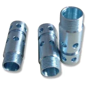
A union strainer is a T-shaped fitting with a removable screen, and it is the one fluid component whose requirement is fundamentally different from every other fitting on this site: its own flow path is deliberately restricted. Every other part on these pages is designed to minimise resistance. A strainer is designed to create resistance, and to create it in a predictable and stable way, and the whole part is a tension between those two requirements.
Which means the strainer’s specification is not about tightness. It is about how much it restricts, how consistently it restricts, and what it does when it is dirty.
What the screen does to the flow, and why that is the specification
A strainer reduces the flow through it, and the amount of reduction depends on the screen’s open area, the mesh size, and the shape of the opening.
- Open area is the number that matters, and it is not the same as screen size. A screen specified as a mesh count tells you the particle size it will capture; it says nothing about how much it will restrict, because a square mesh blocks roughly twenty-five percent of the projected area before any fouling, and a pleated or a woven screen’s blocked fraction is different again.
- Pleated screens exist specifically to raise open area and reduce pressure drop at a given capture rating. A pleated element has several times the surface area of a flat one in the same envelope. So if a strainer has a low pressure drop at a high capture rating, the screen is pleated, and if it has a high pressure drop it is flat, and the two have very different pressure-drop behaviour as they foul.
- The restriction is a specified, permanent part of the system. A strainer has to be included in the system’s pressure-drop calculation at its clean condition. This is why the clean pressure drop or the clean flow at a stated pressure is a functional requirement and should be stated – because it is what the customer actually needs, and because it is what makes a strainer comparable to another strainer.
Direction of flow, and it has to be on the drawing
A strainer is asymmetric. This sounds trivial and it is the most commonly missing item on this part.
- The screen’s face that captures the particle is not the same as the side the flow enters. A flat screen is normally installed with the flow entering the flat face, so the captured particle sits on the upstream surface and can be blown through or washed into the system if the flow reverses. A pleated screen is normally installed with the flow entering from the inside of the pleats, so the particles are trapped inside the element where they cannot be carried through.
- Reversed flow is not hypothetical. A pump that stops, a system that refills, a check valve that fails – and a strainer installed in the wrong direction will have pumped its accumulated debris straight into the downstream system. This is a real and documented failure mode.
- So the drawing must show the flow direction, and it must be marked on the part. An arrow stamped or etched on the body is the minimum and it should be on the assembly drawing as well. Where the part is symmetric enough that it could be installed either way, the part is wrong.
The screen, and what happens when it fouls
A strainer that is specified only for its clean condition is specified for the first five minutes of its service life. The behaviour under fouling is the part that decides whether the strainer is successful.
- Pressure drop rises as the screen blocks. On a low-fouling service the rise is slow. On a service with particulates, the rise is fast and it can be dramatic. Two design responses: a larger element so there is more open area to fill, and a differential pressure indication so the user knows when it needs cleaning.
- Blowout is the failure mode to design against. If the strainer cannot be cleaned before the differential pressure exceeds the body’s rating, the body fails – and a body’s pressure rating is normally its weakest point. This is why a strainer’s pressure rating must be stated and it must be the rating at the clean condition, and it is why many strainer designs have an explicit maximum differential pressure that the user is told not to exceed.
- Where the strainer is on a pump suction, the fouling behaviour matters more, because a restricted suction will cavitate the pump. This is a specific and important case, and on pump suction the strainer is often selected for open area first and capture second.
- Screen material is part of this. A screen that is itself a corrosion product source, or one whose captured particles can embed in it and corrode it, is a self-inflicted contamination problem.
The screen element’s retention, and the seal that makes it drainable
A union strainer’s screen is removable by opening the union, and the removal is what makes the part a strainer rather than a permanent filter. Three requirements follow from that, and they are specific.
- The screen’s seating must seal when the union is closed, and it must not seal when the union is opened far enough. So the screen has two positions: a sealing position and a service position, and the design has to distinguish them. This is a geometry requirement that is not obvious and that a drawing should express.
- The body must drain. A union strainer is usually installed with the drain at the bottom, and the screen is withdrawn downwards so that the captured debris and the liquid come out with it. That is the entire reason for the union design, and it is worth stating the installation orientation as a requirement because a strainer installed upside down is a strainer that cannot be cleaned properly.
- The screen’s removal path must clear the body’s internal features. A pleated element that cannot be withdrawn without catching on an internal shoulder will not be serviceable, and this is a design-stage check rather than something discovered at the customer’s installation.
The two unions, and why they are the part’s weak point
A union strainer has at least two unions – one at the inlet, one at the outlet – and on some designs a third at the screen’s cover. Every union is a joint that will be opened and closed over the fitting’s life, and each one has the same three requirements.
- The union’s thread, and whether it is a metal-to-metal interference seal, a tapered seal, or an elastomer-seated connection. On a union that will be opened frequently, a metal-to-metal taper will be damaged on the first removal and a washer or an O-ring is the better answer – and the washer’s thickness becomes a compression set that affects the joint’s tightness over time.
- The union’s sealing face’s flatness and finish, which is functional and normally specified loosely. A union’s face has to be flat and clean, and a damaged face is the most common reason a union fitting leaks.
- The union’s thread’s engagement and the torque required. A union that requires a large torque will be overtightened by an operator and it will distort. A union that requires very little will leak. The target is the lowest torque that will seal reliably.
And one specific material consequence: the two unions are the part’s wear items. They will be opened, and their threads will gall if they are a dissimilar pair. So the material pairing across the joint – the body against the union’s nut, and the nut against whatever the fitting connects to – is a real consideration and it is where a stainless steel body’s unions tend to seize.
A strainer’s material is the fluid’s decision, plus one extra requirement
Carbon steel, 304 and 316 stainless steel, aluminium and brass, with the final grade fixed at the drawing review. On a strainer the material decision is driven by the fluid and by one specific extra requirement.
- 316L is the normal choice for a stainless steel strainer, on the same chloride logic as elsewhere, and a strainer’s screen is usually stainless steel too.
- The screen’s material should be considered separately from the body’s. A common pairing is a 316L body with a 304 or a 316L screen, and where the service is mildly corrosive a lower grade screen is acceptable because it is replaceable. Where the fluid is chloride-bearing, the screen must be 316L as well, and where the fluid is a food or a pharmaceutical product the screen’s material and its surface finish are a documented requirement.
- Brass is a good material for a strainer body in water and general service, and it is easy to machine. Its limitation is dezincification in a wet service, which on a strainer is more serious than on a fitting because the body is a pressure boundary in the same way.
- Carbon steel is used where the fluid is benign and it needs protection, and on a strainer a carbon steel body in a wet service will rust internally and the rust will carry into the downstream system.
A rougher bore finish costs the strainer pressure drop it was meant to save
Natural, plated or coated per the print, with the finish inspected with the dimensional report on the first article. Three specific items on this part.
- The internal bore’s finish, which is a flow surface and affects the strainer’s pressure drop. A rougher internal surface is a slightly higher pressure drop, and on a part where pressure drop is the specified parameter, this is a small but real contributor.
- The union’s threads, where a plating would change the fit and would gall and would flake at the roots. On a union that will be opened and closed repeatedly, this is a genuine hazard – a plated union thread will seize.
- The sealing faces, which should be unmasked and preferably polished, because that is what makes a union re-seal reliably on its second and third removal.
A screen that is not concentric to the body will not seat
+/-0.01 mm on turned and milled features, capability checked on the first article. On a strainer the flagged dimensions are the flow path, the screen seat, and the unions.
- The screen seat’s diameter and its concentricity to the body’s axis, because a screen that is not concentric to the body will seal unevenly and will leak.
- The screen’s diameter and its thickness tolerance, to the screen element’s specification, because the screen has to fit the seat and its thickness affects the pressure drop.
- The capture rating or the mesh, as a specification in its own right, with a method of verification.
- The clean pressure drop, or the clean flow at a stated pressure, as a functional requirement with a stated test method.
- Each union’s thread, gauged, and each union’s sealing face’s flatness.
- The body’s pressure rating, stated at the clean condition, and the maximum differential pressure stated as well.
- Bore diameters, so that the pressure drop can be calculated.
A capture rating has to be tested, not read off a mesh guess
- Clean pressure drop or clean flow at a stated pressure, on a sample and ideally on every part. This is the test that tests the specification and it is quick.
- Screen capture verification, by test if a specific capture rating is specified and by visual or instrument check if a mesh is specified.
- Screen seat concentricity and diameter, and the screen’s fit in it.
- Each union’s thread gauged and each sealing face’s flatness inspected.
- A functional leak test on the assembled strainer with the screen fitted and the unions closed, at the specified torque – and it is worth also opening and closing it once before the test, because a union that will not re-seal after one opening is a common and expensive finding.
- Flow direction marking verified on the part and confirmed against the drawing.
- Batch records filed so a repeat order starts from approved data, and so that the screen’s specification and the approved pattern are both traceable.
Fluid, flow, pressure, particulate, and cleaning interval
What is the fluid, what is the flow rate and pressure, and how particulate is it – and how often will this strainer be cleaned? Those four answers determine the whole part. A clean service with a low flow rate can be a modest screen in a simple body. A dirty service with a high flow rate needs a large pleated element with a lot of open area, a strainer that will foul quickly, and a differential pressure indicator – and it may need a different design entirely, such as a basket strainer or a duplex arrangement. The fouling rate also determines whether the clean pressure drop is even the right number to specify, or whether the design should be rated for a partly-fouled condition. And the cleaning frequency determines whether the unions need to be designed for frequent service, which changes the sealing method from a metal-to-metal taper to an elastomer-seated or a gasket-seated union and, with it, the service life of the joint. None of these can be guessed from the nominal size and the connection type, and all four are one line on an enquiry.
CNC Machining Parts is the parent range for parts like this one; the overview page gathers the tooling logic, finishing options and tolerance notes that apply across the family.
Specifications
| Item | Stainless Steel Union Strainer Fitting |
|---|---|
| Brand | AUNOV |
| Designing | Quotation follows the print, not a catalogue – samples are reverse-measured into a controlled drawing; changes are priced before they are made. |
| Tooling | Our toolroom covers die design, wire-cut EDM and maintenance, so die cost stays transparent, and the charge is refundable against agreed volumes. |
| Samples | Sample and first article are the same discipline here: measured, reported, then approved. |
| Materials | Carbon steel, 304 / 316 stainless steel, aluminium and brass are all held in stock; the final grade is fixed with the drawing review. |
| Surface finish | Natural, plated or coated – the print decides, and the agreed finish is logged; the finish is inspected with the dimensional report on the first article. |
| Processing | Turn-mill machining, critical diameters finished in one setup; batch records are filed so a repeat order starts from approved data. |
| Equipment | Bar-fed CNC turning centres plus 3- and 4-axis machining centres, with CNC turning centres for secondary operations and CMM inspection. |
| Tolerance | +/-0.01 mm on turned and milled features; capability is checked on the first article before the run continues. |
| Delivery terms | FOB, with DDP offered for EU and US addresses, payment by T/T, L/C at sight or D/P; repeat orders reuse the approved first article. |
Related Products


Request a Quote for This Part
Send a drawing or sketch — get material advice, tooling cost and a per-piece price within 24 hours (working days).