
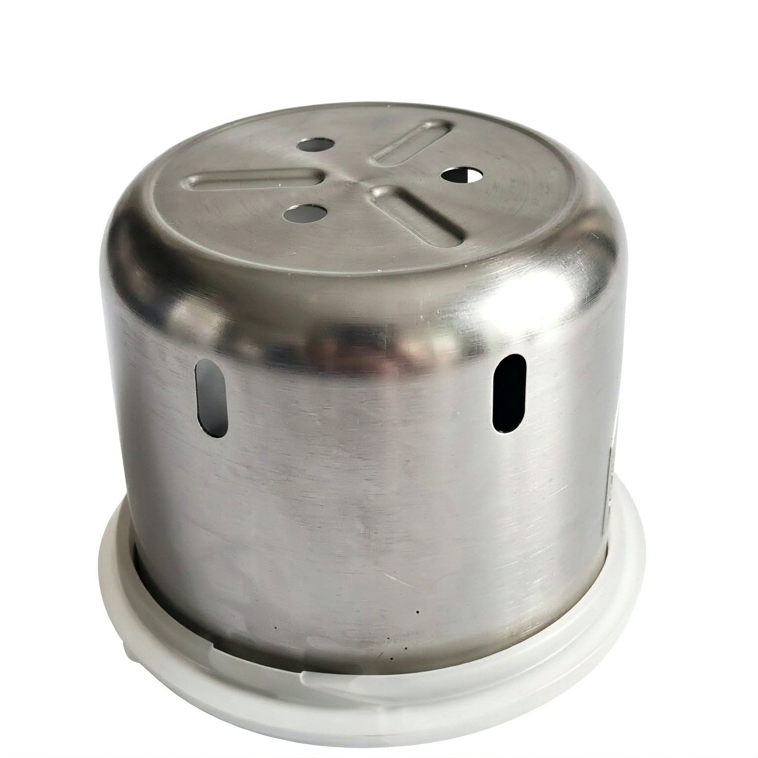
A gyro housing is a resonance problem, and it is the one part where stiffness is the whole specification
A hydroformed aluminium gyro housing holds a gyroscope – a spinning mass that has to keep its orientation, and that senses orientation by measuring the forces on a spinning rotor. That means the housing’s only job is to be rigid and to be quiet in resonance, and everything about its specification follows from that. It is the most stiffness-critical part in this entire family, and the requirements on it are orders of magnitude tighter than a bracket’s, expressed in different units, and checked in a different way.
The route is a tube or sheet preform, hydroformed into the finished contour, trimmed, then annealed and finished. We run mechanical presses 5 to 250 T plus hydraulics 250-500 T with in-line annealing, with in-house toolmaking keeping dies and fixtures maintained. Turned secondary features to +/-0.03 mm and as-drawn walls to +/-0.1 mm, with finer bands confirmed from capability data before quoting. 1050, 3003, 5052 or 6061 aluminium in 0.5-3.0 mm stock, with the temper matched to the forming depth or machining route of this housing. Finish is selected from the drawing – plating, coating, anodising or passivation – with alternatives quoted with the quotation and samples approved in writing. This page is about stiffness, resonance, and the four things that make a gyro housing different from every other housing in this catalogue.
The housing is a mass-spring system, and the spring is the drawing
A gyroscope senses by detecting a force on a spinning mass. External vibration produces forces on that mass that are indistinguishable from the forces the gyroscope is trying to measure. So the housing has a job that is the opposite of most housings’: most housings need to isolate the contents from vibration, and a gyro housing has to transmit nothing to them. Four consequences, all of them dimensional:
- The housing’s own resonances must not sit in the operating band. A structure has an infinite set of modes. Where a mode coincides with a vibration present in the environment, the housing amplifies that frequency and the gyro senses it as a real force. This is a mode-placement problem and it is the primary design requirement.
- The mounting points determine the modes. The housing’s stiffness is a property of the housing and its mounting, not of the housing alone. A housing that is stiff when bolted to a rigid plate can be floppy when bolted to a structure that has its own resonances. So the mounting interface has to be part of the design, and the interface stiffness and interface damping are what actually set the system’s behaviour.
- Wall thickness is the primary stiffness variable and on a hydroformed part the wall is set by the preform. Aluminium’s modulus is fixed, so the stiffness comes from the section’s geometry and its thickness – and a hydroformed shell’s stiffness is dominated by its thickness and its curvature, both of which are determined by the preform and the tooling rather than by a machining allowance.
- Mass and stiffness are coupled. A heavier housing is stiffer, which raises its modes, which can be good or bad depending on where the modes need to be. Adding material is a crude but real way to move a resonance, and on a part where the mass budget matters it is a trade that has to be made deliberately.
Turned features, and where the tight band actually goes
Turned secondary features to +/-0.03 mm is the stated band, and on a gyro housing it belongs to a short and specific list, because on this part the machined features are the mounting and adjustment features and nothing else:
- The mounting holes and their positions. These set how the housing is attached, and therefore how stiffly it is attached. Their positions are a true position requirement against a named datum, and their size affects how the mounting interface behaves – a larger hole on the same fastener gives a more compliant mount and a lower interface stiffness.
- Any locating spigot, dowel, or register. A register that centres the housing in its mount controls the alignment between the housing and the sensor, and misalignment here is a direct calibration error.
- Any adjustment or trimming feature. On a gyro product, a small adjustment on the housing or its mount is often how the calibration is held – and on a part with a mode requirement, an adjustment that changes the stiffness is a calibration that changes the resonance. These two things interact.
- Mass trimming features, if used. On a high-performance gyro the housing is often trimmed to put its centre of mass exactly where it needs to be. That is a mass-balance requirement, not a cosmetic one, and it is a machining feature with a tight tolerance.
As-drawn walls, and why the material specification is the tolerance
As-drawn walls to +/-0.1 mm is the stated band, and on a gyro housing it is a stated band with an unusual consequence. The wall is the primary stiffness variable, so a wall that varies by a tenth of a millimetre is a stiffness that varies by a tenth of a millimetre’s worth – and on a part whose resonances are placed precisely, that is a shift in the mode frequencies. If the gyro’s calibration is sensitive to a resonance near the operating band, then the wall’s variation is a calibration variation.
This leads to a requirement that is specific to this part type and that is worth stating plainly: on a gyro housing, the wall’s thickness variation may need to be tighter than the commercial default, and the way to achieve that is to specify the material’s thickness, not the part’s dimension. A wall held to print is a material specification. If the mode placement requires a wall band narrower than commercial sheet, the material has to be bought to a thickness specification – and that is a purchasing decision with a cost and a lead time, and it needs to be known at quotation rather than discovered when the modes measure wrong.
Hydroforming, and why it is the right choice here
The hydroforming process suits this part for a specific reason, and it is worth being clear about it because the usual reasons do not apply here. On a gyro housing:
- Wall uniformity is the reason, not the shape. A hydroformed shell has a wall that is far more uniform than a drawn one, because pressure is applied uniformly from inside rather than through a directional material flow. On a stiffness-critical, mass-critical part, that is worth a great deal – a wall that is uniform means the stiffness calculation is valid everywhere.
- The compound contour contributes real stiffness. A dome or a compound form is structurally stiff in a way a flat panel of the same thickness is not, and hydroforming gets that stiffness without adding material. On a part where both mass and stiffness matter, that is the ideal trade.
- No seam. A seam in a gyro housing would be a stiffness discontinuity and a stress concentration in a part that is intended to be inert. A hydroformed part has no seam.
The costs, stated honestly, because they are the reason this is a considered choice: cycle time makes it a prototype and low-to-medium-volume process; dimensional repeatability across a batch is harder than a stamping’s, so a mode-placement requirement has to be proved from capability data rather than assumed; and anything non-axisymmetric has to be machined afterwards, which on this part is the mounting features and is entirely appropriate.
Material, and the three that matter
1050, 3003, 5052 or 6061 aluminium in 0.5-3.0 mm stock, with the temper matched to the forming depth or machining route. On a stiffness-critical part:
| 1050 | The purest, the most ductile, and the best surface. On a gyro housing the temper is the variable that matters and 1050 in a controlled temper gives the most predictable forming behaviour – which for a part whose wall is the stiffness means the most predictable stiffness. |
|---|---|
| 3003 | Slightly stronger with good formability, and the general-purpose choice. It is a reasonable answer on a gyro housing where the forming depth is moderate. |
| 5052 | Considerably stronger, with better corrosion resistance, and it forms less cleanly. Worth considering where the housing’s stiffness has to come from the material rather than from the geometry. |
| 6061 | The machinability grade, and on this part that matters more than usual because the mounting and adjustment features are machined and their accuracy is the tight band. Its draw formability is the poorest of the four, so a deep hydroform in 6061 is harder and needs more care in the anneal schedule. |
On the temper, and this is the point worth raising at review: for a non-ferrous aluminium the temper is a meaningful fraction of the material’s strength, and the temper affects both how the part forms and what its residual stress is. A part whose specification is “aluminium, 1.0 mm” without a temper has not been specified for a stiffness application.
Finishing, and the three surfaces that matter
Finish is selected from the drawing – plating, coating, anodising or passivation – with alternatives quoted with the quotation and samples approved in writing. On a gyro housing:
- Mask the mounting surfaces and the register. A coating on the mounting face or on a locating spigot changes its dimension, and on this part those are the features that determine how the housing is attached and therefore how stiffly it is. This is a functional masking requirement.
- Consider whether a coating is acceptable at all on the mounting interface. A coating adds a layer whose stiffness and whose damping differ from the metal’s, and on a part where interface stiffness and damping set the system’s behaviour, a thick coating is a change to the design and not just to the appearance.
- Anodising is the natural finish here. It is hard, dimensionally very well behaved, corrosion-resistant, and it is the coating that changes the part’s least. It also has to be masked from the mounting surfaces, which is a per-part operation.
A solid block, where stiffness allows it
Eight things, and this list is longer on the requirement side than on the dimensional side, because that is what this part is:
- Mode placement requirement – the frequency band the housing must not resonate in, and the mode shapes that matter. This is the primary requirement and it is almost never on a mechanical drawing.
- Mounting interface definition – the hole pattern, the fastener size, whether the mount is bolted, bonded, or located by a spigot, and the interface’s flatness.
- Wall thickness held to print, with the tolerance required – and where that tolerance is tighter than the commercial default, the material specification that achieves it.
- Material grade and temper, confirmed in writing, with the temper stated rather than defaulted.
- Mounting feature positions as true position to a named datum, at the tight band, because those positions set the interface stiffness.
- Any mass-balance or centre-of-mass requirement, with its tolerance, if the product has one.
- Which surfaces are masked, and whether dimensions apply before or after finish.
- Any second material interface – a sensor can be potted, bonded, or separately mounted, and how the sensor is coupled to the housing is part of the housing’s specification.
How much of this housing could be machined solid?
How much of this housing could be a machined solid block? On a part this stiffness-critical, a machined aluminium block has far better dimensional control than any formed shell, a fully controllable mass distribution, and no dependence on the forming process for its properties. It is more expensive per part and much heavier. The hydroformed shell wins where mass matters and the volume is low enough to justify it; the machined block wins where absolute dimensional confidence matters more than mass. It is worth establishing at enquiry which of those the product is optimising for, because a gyro housing designed for one and manufactured as the other will meet its dimensional spec and still perform worse than intended – and the reason will be a mode that moved.
The design decisions behind a part like this — draw ratio, wall thinning, radii and trim — are worked through with numbers in our deep drawn covers guide, and the Precision Deep Drawn Parts pages collect the rest of the family.
Specifications
| Item | Hydroformed Aluminum Gyro Housing |
|---|---|
| Brand | AUNOV |
| Designing | Quotation follows the print, not a catalogue – DFM notes are returned before any tooling is cut; changes are priced before they are made. |
| Tooling | Our toolroom covers die design, wire-cut EDM and maintenance, so tooling lead time stays under our control, and the charge is refundable against agreed volumes. |
| Samples | First-article samples ship with a dimensional report and material certificate, so the approved first article becomes the gauge reference, and production starts only after your written sign-off. |
| Materials | 1050 / 3003 / 5052 / 6061 aluminium, 0.5-3.0 mm stock – temper matched to the forming depth or machining route of this housing. |
| Surface finish | Finish selected from the drawing: plating, coating, anodising or passivation; alternatives quoted with the quotation, samples approved in writing. |
| Processing | Tube or sheet preform, hydroforming into the finished contour, trimming, then annealing and finishing. |
| Equipment | Mechanical presses 5-250 T plus 250-500 T hydraulics, with in-line annealing, with in-house toolmaking to keep dies and fixtures maintained. |
| Tolerance | +/-0.03 mm on turned secondary features, +/-0.1 mm on as-drawn walls; finer bands confirmed from capability data before quoting. |
| Delivery terms | FOB Ningbo or Shanghai, payment by T/T or L/C, quoted in USD or EUR; price breaks tie to annual volume. |
Frequently Asked Questions
Why is a gyro housing hydroformed instead of machined from solid?
Hydroforming pushes the aluminium against a single cavity in one shot, so the wall thickness is uniform and the stiffening is built into the shape rather than cut away. Against a machined block it removes the material cost and the residual stress of removing most of a billet, which matters on a part whose whole specification is stiffness.
What wall thickness tolerance does a hydroformed gyro housing hold?
The as-formed wall is held by the tool and the pressure profile, typically to a few hundredths of a millimetre on the critical faces, with the bore or mounting surface verified on the CMM. Because the tolerance is set by the die rather than by removing metal, it repeats across the run instead of drifting part to part.
Which aluminum grades are used for gyro housings?
A 5xxx or 6xxx grade is chosen for the stiffness-to-weight and the way it responds to hydroforming, with the temper picked so the part stays dimensionally stable after finishing. The grade is the tolerance here, because the housing’s job is to be a stable mass-spring system.
How is a hydroformed gyro housing finished for stiffness?
Hard anodising is the usual finish, not a decorative coat, because it adds a wear and corrosion layer without changing the geometry that the stiffness depends on. The three surfaces that matter – the mounting face, the bore, and the sealing land – are finished to their own bands and checked separately.
Related Products



Request a Quote for This Part
Send a drawing or sketch — get material advice, tooling cost and a per-piece price within 24 hours (working days).