
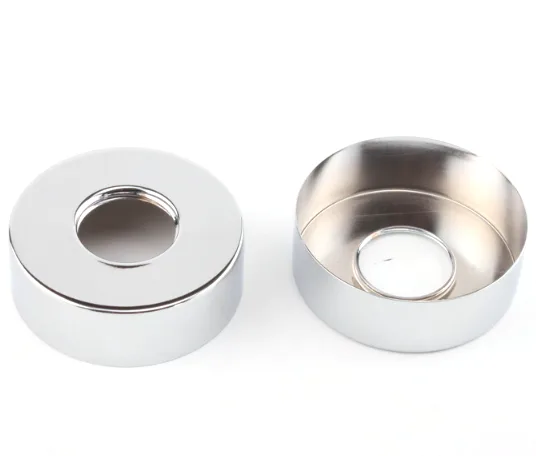
A centre hole turns a cup into a registered part, and registration is a tolerance problem
A drawn cup with a centre hole is a cup with a hole in its base, and that one feature changes the part from a container into a component. Without a centre hole a cup is simply a shape that holds something. With a hole, the cup can be located, vented, fed, attached, or pressed onto something – and every one of those uses makes the hole’s position a functional requirement rather than a cosmetic one. The hole also creates a forming problem, because a drawn base with a hole in it is materially harder to form than a solid one.
We draw these progressively through several stages, annealed between draws, then trim and pierce, and batch records are filed so a repeat order starts from approved data, on 5-250 T mechanical presses and 250-500 T hydraulic presses with annealing furnaces in line, CNC turning centres for secondary operations, and CMM inspection. Flange and rim dimensions to +/-0.05 mm with the wall controlled by the draw, and capability is checked on the first article before the run continues. Carbon steel, 304 and 316 stainless steel, aluminium and brass are all held in stock, with mill certificates and heat numbers accompanying the first article. Plating, powder coating, anodising or polishing per the print, and the agreed finish travels with the part number. This page is about what a centre hole does to a drawn cup, in the forming and in the function.
Forming: a hole in the base is a forming problem before it is a functional one
Drawing a cup with a hole in its base is harder than drawing a solid one, and the difficulty is in the material’s flow. Four things happen:
- The material has to flow around the hole. In a solid-base cup the base’s material is supported by the die across its whole area. With a hole, the material immediately around the hole has less support, and the base is weaker there – so the base will bulge or dish preferentially around the hole rather than uniformly.
- The base’s flatness is lost around the hole. This is the same dished base problem as on any drawn pan, and it is worse with a centre hole because the unsupported region is in the middle where the eye is drawn to it. A cup whose base dishes around its hole will not sit flat, and it will not seal if it is used as a seal.
- The hole’s edge is a stress riser. The base around a hole is under tension from the draw, and the hole’s edge concentrates it. A hole with sharp sheared edges in a base under tension is where a crack would start if the cup is handled roughly or flexed.
- The hole is usually pierced after the base is formed, and piercing a formed base means the punch sees a curved, work-hardened surface. The hole will be slightly oval, slightly out of square to the base, and the burr side is not simply determined. If the hole has to be accurately round, it has to be machined or pierced in a flat preform.
Registration: what the hole actually has to do
Once the hole exists, it has a job, and the job determines its tolerance. Five common jobs, and they are not interchangeable:
| Locating pin or dowel | The hole takes a pin that positions the cup. Then the hole’s size sets the fit, its position sets the registration, and its roundness sets how the pin sits. This is a true position requirement against the cup’s axis, and a tight size band. A press fit here is a specified interference, not a nominal. |
|---|---|
| Attachment or fastening | Something is riveted, screwed, or pressed through the hole. Then what matters is the hole’s position relative to the cup’s features and its edge distance, and the bearing area around it. A hole too close to the base’s edge will tear there. |
| Vent or drain | The hole lets air or liquid through. Then its size is a flow requirement, its position is a drainage requirement – a vent hole that is not at the high point does not vent – and the burr direction may matter if it is in a wet path. |
| Feed or dispensing | Material flows through the hole. Then the hole’s size is a flow rate requirement, its edge condition matters because a burr will restrict or redirect the flow, and the base’s flatness around it affects how evenly it discharges. |
| Visual or marking | The hole is decorative or a registration mark. Then a general tolerance is enough, and this is the only case where it is. |
Roundness, and the formed hole’s problem
This is worth dwelling on because it is a recurring finding on this part type. A hole pierced in a formed base is not round, and three requirements follow:
- Specify roundness separately from size wherever the hole takes a pin or a shaft. A hole can be perfectly in size and visibly oval, and an oval hole takes a pin unevenly and locates poorly. Roundness is a separate callout from the diameter’s size tolerance.
- Where tight roundness is needed, machine the hole or pierce it flat. A hole machined in a secondary operation on a CNC is round and can be concentric to the base. A hole pierced in a flat preform before the base is formed is round but is located in the flat, which means its position relative to the base’s axis is set by the preform’s geometry. Either route works; what does not work is assuming a pierced hole will be round.
- The position of the hole relative to the base’s outside diameter is what matters for registration, and on a drawn cup it is set by the preform and the feed. A drawing that states the hole’s position as a coordinate from the base’s edge rather than as a true position to a named axis is harder to control and easier to misread.
A cup’s rim is both its locating feature and often its seal
Flange and rim dimensions to +/-0.05 mm is the stated band, and on a cup with a centre hole it applies to:
- The rim or flange, which is the cup’s mating feature – it locates the cup, and often it seals. Its flatness and its position relative to the hole’s axis are functional, because a flange that is not flat and concentric to the hole will not seal evenly.
- The hole, if the hole is machined or if a tight band is genuinely needed. A pierced hole’s size comes from the punch and drifts with tool wear, so a tight band on a pierced hole is a maintenance-interval question.
- Nothing else needs a tight band. A drawn cup’s wall and general profile are adequately held at the drawn tolerance, and a wall held to print is a material specification rather than a press one.
Material, and the base’s behaviour
Carbon steel, 304 and 316 stainless steel, aluminium and brass are all held in stock, with mill certificates and heat numbers accompanying the first article. On a cup with a centre hole, the material choice affects the base’s dish and the hole’s edge:
- 3003 or 1050 aluminium dishes least, which matters where the base has to be flat. It also forms the smallest hole cleanly, because a softer material deforms around the punch rather than cracking at the hole’s edge.
- SPCC or DC01 carbon steel is a good compromise and is the default for a general cup. It dishes somewhat around a centre hole, and its hole edges work-harden and resist further deformation – which is helpful for a hole that has to stay round.
- 304 stainless steel work-hardens more, which helps the hole’s edge hold its shape, and it dishes more around the hole because it is stiffer and does not conform. 316 where the environment is corrosive.
- Brass is used where a warm appearance or a specific corrosion behaviour applies, and it forms the smallest hole cleanly.
Finishing, and the base’s interior
Plating, powder coating, anodising or polishing per the print, and the agreed finish travels with the part number. On a cup with a centre hole, four points:
- The hole’s edge is where the coating is thinnest and where burrs are. On a cup whose base is visible or whose hole is a functional feature, the hole’s edge condition is a quality requirement rather than a handling one.
- Coverage on the base’s interior is the same coverage problem as any drawn cavity – thinner inside than outside, and thinnest in the transition from the base to the wall. On a cup that holds or dispenses something, the interior’s surface condition is a functional consideration.
- Masking, where the hole takes a pin. A plated hole is smaller than a bare one, and if it is a locating fit the plating has to be specified post-plate or masked. This is a real fit requirement on a registration feature.
- Plating thickness against the rim’s dimension. On a small cup, a powder coat at 60 to 120 microns is a meaningful fraction of the +/-0.05 mm rim band, so whether the rim’s dimension is before or after coating has to be stated.
A two-piece cup can be easier than one with a hole
Eight things, and the first two are what turn a hole from a feature into a specification:
- What the hole is for – locating, fastening, venting, dispensing, or decoration. Every tolerance follows from this, and it is the item most often missing.
- Roundness on the hole, separately from its size, wherever it takes a pin, a shaft, or a flow.
- True position of the hole to a named datum, normally the cup’s axis, rather than a coordinate from the base’s edge.
- Whether the hole is pierced in a flat preform or machined after forming, because that determines whether it is round and where its position comes from.
- Edge distance from the hole to the base’s edge, so the base does not tear there under handling or clamping.
- Flange and rim flatness and concentricity to the hole’s axis, at the tight band, since the flange is the seal and the registration reference.
- Wall thickness held to print, with the minimum location, which on a cup is at the punch nose in the base – the same region as the hole.
- Material grade, and which surfaces are masked, with dimensions stated before or after finish.
Does the hole need to be in the base?
Does the hole need to be in the base, or could the cup be made with an open end and a formed-in-hole? It sounds like a strange question, but there are cases where a hole in a deep drawn base is the hardest feature on the part and a construction that avoids it is much simpler – a cup formed from a tube with a pierced or machined end, for instance, or a cup whose base is a separate machined piece. The centre hole in the base is usually the right answer because it makes the cup a single piece and gives it a continuous interior. But on a cup where the base has to be very thick, or very precisely flat, or very hard, a two-piece construction can be both easier to make and better performing. It is worth asking when the base’s requirements are demanding, because that is exactly when the two-piece option becomes competitive.
Not sure whether to draw, machine or weld this geometry? The guide to deep drawn covers compares the three routes and shows where each one wins; the full Precision Deep Drawn Parts range is linked from the overview page.
Specifications
| Item | Stainless Steel Drawn Cups with Center Holes |
|---|---|
| Brand | AUNOV |
| Designing | Send drawings, or send a sample to be measured – unusual walls, threads or tolerances are feasibility-checked first; changes are priced before they are made. |
| Tooling | Tooling is built and held under your part number, so tooling lead time stays under our control, and ownership is confirmed on the quotation. |
| Samples | Pre-production samples come with a full inspection report, so the approved first article becomes the gauge reference, and production starts only after your written sign-off. |
| Materials | Carbon steel, 304 / 316 stainless steel, aluminium and brass are all held in stock; mill certificates and heat numbers accompany the first article. |
| Surface finish | Plating, powder coating, anodising or polishing, per the print; the agreed finish travels with the part number. |
| Processing | Progressive drawing through several stages, annealed between draws, then trim and pierce; batch records are filed so a repeat order starts from approved data. |
| Equipment | 5-250 T mechanical presses, 250-500 T hydraulic presses and annealing furnaces in line, with CNC turning centres for secondary operations and CMM inspection. |
| Tolerance | +/-0.05 mm on flange and rim dimensions, wall controlled by the draw; capability is checked on the first article before the run continues. |
| Delivery terms | FOB Ningbo or Shanghai, T/T with deposit and L/C for larger runs; call-off schedules are supported. |
Frequently Asked Questions
What keeps the center hole concentric with the outside of a drawn cup?
The center hole is located by the same punch and die that form the cup, so bore-to-outside concentricity is set in one setup rather than measured in after a second operation. On a stainless steel cup we hold that relationship to a few hundredths of a millimetre and verify it on the CMM, because a hole that runs out from the OD is the first thing that fails when the part has to locate on a shaft.
Can the center hole be punched before the cup is drawn?
Not usually. Punching the hole first lets the wall distort and the bore go out of round as the metal flows, so on a cup with a functional center hole we draw first and pierce or broach afterwards while the part is supported. The trade-off is a second operation, but it is what keeps the hole round and the wall where the print calls for it.
Which stainless steel is best for a cup with a center hole?
Most are 304 or 316. 304 covers general and washdown use; 316 adds molybdenum for chloride and marine duty. The grade is chosen for the environment rather than the form, and mill certificates with heat numbers accompany the first article so the shipped cups trace back to the coil.
What is the minimum order quantity for drawn cups with center holes?
Production runs start at 1,000 pieces, with tooling made in-house to your print rather than a catalogue size. We return a quote within 24 hours of the drawing, and first articles are measured on the CMM before the full run begins.
Related Products


Request a Quote for This Part
Send a drawing or sketch — get material advice, tooling cost and a per-piece price within 24 hours (working days).