
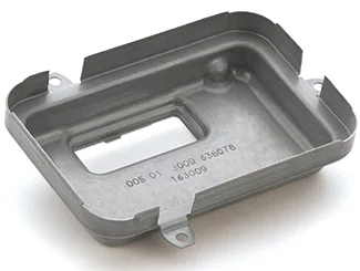
A chassis tray is an enclosure, and enclosures are about seams, not walls
A deep drawn power supply chassis tray is a box: a bottom, four walls, and flanges that tie it to a cover. The walls are the easy part. What actually determines whether a chassis tray works is the set of seams – where the cover meets the tray, where a board mounts, where a cable enters, and where the tray is fixed to the equipment it lives in. A drawn tray’s geometry is unremarkable; its seam design is where the engineering is, and where most of the field problems come from.
We draw these progressively through several stages, annealed between draws, then trim and pierce, with in-process checks between stages rather than only at the end, on mechanical presses 5 to 250 T and hydraulic presses 250-500 T with in-line annealing furnaces, with CNC turning centres for secondary operations and CMM inspection. General tolerance on drawn sections is +/-0.1 mm with +/-0.03 mm on machined seats, and finer bands are confirmed from capability data before quoting. Materials held include carbon steel, 304 and 316 stainless steel, aluminium and brass, with special grades sourced to the drawing when volumes justify. Plating, powder coating, anodising or polishing, with alternatives quoted with the quotation and samples approved in writing. This page is about seams, flatness, and the details that make a chassis either compliant or noisy.
Seam 1: the cover joint, and why a drawn tray is usually conductive
On a power supply, the chassis is part of the enclosure and often part of the earth path. The cover joint has to do two things at once – provide an electrical bond across the seam for safety and for EMI, and provide whatever mechanical retention is needed. These are in tension, and the resolution is a design of the joint rather than of the metal:
- A drawn tray is electrically continuous around its shell, which is good – the walls, the bottom and the flanges are all one piece and all at the same potential. That removes the bonding problems that a bolted or welded fabrication has.
- The seam’s bond depends on the contact area and the surface condition. A flange face that is flat and uncoated makes a good bond. A flange face that is painted, or a powder-coated flange, is an insulator and the bond goes through whatever fasteners happen to pass through it. So on a bonded chassis, the cover’s mating flange must be masked from coating, and that is a masking requirement with a real cost.
- The seam’s electromagnetic performance matters too. A long slot seam is an antenna, and a power supply’s enclosure is often a significant part of its EMI performance. A drawn tray with a formed flange creates a long slot, and the slot’s width and length and the contact along it determine how much it radiates. This is a genuine design parameter and it is not visible on a mechanical drawing.
- The bond resistance should be specified, where the design requires it – typically a low milliohm value measured with a defined method. This is a measurable requirement and it belongs on the drawing for a power supply chassis.
Seam 2: the board and component mounting
The tray’s interior carries the electronics, and the features that mount them have requirements that are specific to a drawn part:
- Mounting holes for heavy components. A transformer or a heatsink mounts through the tray’s bottom, and the load is a shear load in the sheet. On a drawn bottom, the sheet’s thickness is the section, and a heavy component will work the hole oval and then crack around it. Reinforcement – a drawn boss, or a formed dimple – is usually needed, and where the component is heavy enough, a separate insert is the honest answer.
- Standoff positions for the board. These are a pattern of holes or formed standoffs, and their positional accuracy is a real requirement for a board that has to fit. Piercing them in the flat, before the walls are formed, gives the best accuracy – and it is free.
- Heat dissipation. A power supply’s tray is often its heat sink for the losses that are not handled by a heatsink. That makes the wall thickness and the material a thermal requirement rather than a structural one, and it means the interior surface’s condition matters – a plated or coated interior conducts less than bare metal.
Seam 3: cable entry and openings
Every opening in a chassis is a hole in an enclosure, and there are three requirements that apply to all of them:
- Mechanical protection. A raw punched hole exposes the interior to fingers, tools and debris. On an IP-rated enclosure every opening needs a defined treatment – a bushing, a grommet, a grille, or a specific clearance. The IP rating should be a stated requirement and the openings should be listed against it.
- EMC. A hole in an enclosure leaks electromagnetic energy, and the size and the number of holes set how much. A chassis that needs a specific EMC performance has to consider its openings as part of its filtering and shielding design – and vent holes in particular are usually a filtered or mesh-covered feature, not a punch.
- The wall’s local stiffness. A large opening in a drawn wall weakens the wall around it, and on a chassis wall that carries a mounting load this matters. A punched hole close to a formed feature or a wall’s free edge will tear there.
Flatness, and why it matters more here than on most parts
The general tolerance of +/-0.1 mm on drawn sections is reasonable, but on a chassis tray there are two features where flatness is a requirement rather than a preference:
- The cover flange. The flange that the cover bolts to has to be flat for the joint to seal and to bond properly. This is a flatness requirement against a named surface, and it is the one most often missing on a chassis drawing.
- The bottom, where a board or a heavy component mounts. A dished bottom means the mounting standoffs are not all the same height, so a board fitted to them will be stressed, and a heavy component’s load will be carried unevenly. On a chassis this produces intermittent behaviour that is very hard to diagnose, so the flatness is worth stating.
Material, and the conductivity question
Materials held include carbon steel, 304 and 316 stainless steel, aluminium and brass, with special grades sourced to the drawing when volumes justify. For a power supply chassis:
- SPCC or DC01 steel is the standard choice and it is genuinely good here: it is stiff, it forms well, it takes a coating for appearance and corrosion resistance, and it is cheap. Where the chassis is earthed through its flanges, its conductivity is more than adequate.
- Aluminium is chosen where the chassis must dissipate heat, where mass matters, or where an anodised finish is wanted. Its conductivity is about a third of steel’s for structure, which matters for a stiff chassis, and it is better for heat. It also relaxes under sustained bolt clamp load, which on a long chassis bolted at many points is a real consideration – a bolted aluminium joint can lose preload and develop a click.
- 304 or 316 stainless steel where corrosion resistance dominates or where a bare bright chassis is wanted for a visible product. 316 for salt or process environments. It forms less well and springs back more, so the tooling and the tolerances have to account for that.
- Brass where conductivity of the earth path or a specific corrosion behaviour is required, and it is used in some high-specification chassis for its appearance.
Finishing, and the masking that a bonded chassis requires
Plating, powder coating, anodising or polishing, with alternatives quoted with the quotation and samples approved in writing. On a chassis tray the finishing decisions are unusually consequential:
- Mask the cover’s mating flange and any earth bonding point. These must be bare for the joint to bond, and this is the one masking requirement on a chassis that is never optional.
- Coating the interior reduces heat dissipation. If the chassis is dissipating heat into its interior surface, a powder coat or a plating on that surface is a thermal penalty. Where it matters, the interior should be specified bare, plated, or with a thermally conductive coating.
- Mask any threaded feature and any locating pin or spigot, since a coating on a thread will seize and a coating on a spigot will affect the fit.
- Appearance is a product requirement on a visible chassis, and on a visible part a retained colour reference sample is worth more than a colour code.
Drawn tray, or folded and welded chassis
Eight things, and the first three are what turn a tray into a chassis:
- The enclosure requirements – the IP rating, the earth requirement, and the EMC performance, stated so the openings and the seams can be designed rather than guessed.
- Cover flange flatness, against a named surface, plus the masked areas that make the joint bond.
- Bottom flatness where a board or a heavy component mounts, and the mounting pattern with its datum.
- All openings listed, with their sizes, their positions, and their treatment – plain, bushed, grommeted, or filtered.
- Wall thickness, and where the minimum is, – at the punch nose and at the corners.
- Reinforcement where heavy components mount, drawn boss, dimple, or a separate insert.
- Which surfaces are masked, and whether dimensions apply before or after finish.
- Material grade, confirmed in writing, with the thermal requirement stated if the chassis dissipates heat.
Is this a drawn tray or a fabricated chassis?
Is this a drawn tray or a fabricated chassis? A folded and welded or a sheet-metal-fabricated chassis can have a much more complex form – angled mounting faces, integral heatsink fins, complex cut-outs, radiused corners that a draw cannot make – and it can be made from standard sheet. A drawn tray is the right answer where the geometry is a simple box, where volume is high, where the seamless shell is valuable for the earth path and for rigidity, and where a flat-rolled sheet cost matters. It is the wrong answer where the shape is complex. On a power supply with substantial heat dissipation, an extruded or finned chassis is often a better answer than any stamped or drawn one, and it is worth raising at enquiry stage.
The engineering calls behind a part like this — draw ratio, wall thinning, radii and trim — each get worked examples in our deep drawn covers guide; the Precision Deep Drawn Parts pages gather the rest of the family.
Specifications
| Item | Deep Drawn Aluminum Power Supply |
|---|---|
| Brand | AUNOV |
| Designing | Send drawings, or send a sample to be measured – unusual walls, threads or tolerances are feasibility-checked first; changes are priced before they are made. |
| Tooling | Dies, fixtures and gauges are made in our own toolroom, so a die can be re-cut against the approved drawing, and maintenance is tracked against the part number. |
| Samples | Sample parts are measured and reported before submission, so the approved first article becomes the gauge reference, and mass production is gated on that approval. |
| Materials | Materials held include carbon steel, 304 / 316 stainless steel, aluminium and brass; special grades are sourced to the drawing when volumes justify. |
| Surface finish | Plating, powder coating, anodising or polishing, per the print; alternatives quoted with the quotation, samples approved in writing. |
| Processing | Progressive drawing through several stages, annealed between draws, then trim and pierce; in-process checks sit between stages, not only at the end. |
| Equipment | Mechanical presses from 5 to 250 T and hydraulic presses 250-500 T, with in-line annealing furnaces; secondary ops run on CNC turning centres, inspection on the CMM. |
| Tolerance | +/-0.1 mm general on drawn sections, +/-0.03 mm on machined seats; finer bands confirmed from capability data before quoting. |
| Delivery terms | FOB Ningbo or Shanghai, T/T or L/C, with D/P accepted on repeat business; sea or air freight is quoted to your door. |
Frequently Asked Questions
Why are seams the hard part of a drawn chassis tray?
The walls are easy to draw; the cover joint, board mount, cable entry and equipment fixings are where the engineering and most field failures sit. Flange flatness drives the seal, so it is specified and reported rather than assumed.
Is a deep drawn tray better than a folded-and-welded chassis?
For a conductive, single-piece enclosure a drawn tray removes weld seams and the EMI leaks they create; for complex internal features fabrication wins. We advise per the print and quote both so the choice is visible.
What tolerances apply to a drawn power supply tray?
Drawn sections are held to +/-0.1 mm and machined seats to +/-0.03 mm, with finer bands confirmed from capability data before quoting. Flatness of the flange and mounting faces is controlled and reported.
Which materials and finishes are offered for chassis trays?
Carbon steel, 304 and 316 stainless steel, aluminium and brass, with plating, powder coating, anodising or polishing per the print. The typical minimum order is 1,000 pieces with a 24-hour quotation.
Related Products


Request a Quote for This Part
Send a drawing or sketch — get material advice, tooling cost and a per-piece price within 24 hours (working days).