
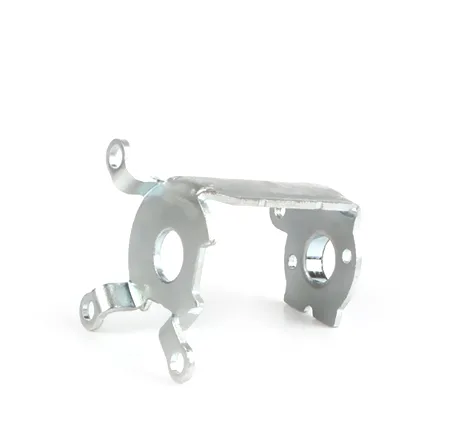
A line clamp bracket fails by cracking, not by rusting
A stainless steel stamped line clamp bracket holds a pipe, a tube, or a cable against a structure. It works by encircling the line and reacting the line’s weight, its vibration, and any pressure thrust the line exerts into a bolted or riveted connection back to the structure it is fixed to. That load path – line to clamp to fastener to structure – is the whole design, and on a stainless steel part the interesting failures are not corrosion failures at all. They are fatigue cracks at the clamp’s opening, at the fastener holes, and at the roots of the formed features.
We coil-feed and blank progressively, then form, pierce or tap in-die, deburr, and plate, on 5-250 T mechanical presses with decoilers and coil feeders, vibratory finishing lines and a full in-house toolroom. Bend positions to +/-0.05 mm and blank outline to +/-0.1 mm, with critical dimensions carrying CMM data with the shipment. Standard stock is carbon steel in SPCC and DC01 grades, 304 and 316 stainless steel, aluminium and brass, with the final grade fixed at the drawing review. Plating, powder coating, anodising or polishing per the print, with the finish inspected alongside the dimensional report on the first article. This page is about the fatigue problem, because it dominates this part’s life.
The opening is where a clamp bracket breaks
A clamp has to open to be installed around the line, and that opening is where the cross-section is interrupted. This creates three separate problems, all of them fatigue problems:
- The section is weakest at the opening. The clamp’s whole job is to squeeze, which puts hoop stress into the band, and the opening is where that band is interrupted. The stress concentration at the opening’s edge is therefore multiplied on top of a section that has already been reduced.
- The edges at the opening are sharp and are loaded. A sheared or punched edge at the opening is a crack initiation site. Under cyclic loading – a pipe that vibrates, a line that pulses, a bracket on a vehicle – a crack starts at that edge and grows until the clamp opens.
- The opening closes and opens repeatedly. Every time the clamp is installed or removed, the opening’s region is plastically deformed. This is a low-cycle fatigue situation, distinct from the high-cycle stress cycling of a vibrating pipe, and low-cycle fatigue is dominated by material ductility rather than by the presence of a notch. This is why a material with good ductility but lower yield strength can outlast a harder material at an opening.
Where the material’s properties actually matter
Stainless Steel is chosen here for corrosion resistance, and it brings two properties that matter more than people expect:
- Work hardening. A stamped stainless steel bracket is harder than its mill condition, and the material at the formed features and the punched edges is harder still. This raises its strength but reduces its ductility – and ductility is exactly what the opening needs.
- No relief from stress concentrations. Steel’s higher ductility lets it yield locally and redistribute a stress peak; stainless steel’s lower ductility means it does not, so a stress concentration is more severe in stainless steel than in mild steel at the same geometry. A bracket designed in steel with a sharp punched edge will fail sooner in stainless steel than the geometry alone suggests.
The practical design responses, in order of effectiveness: increase the section depth away from the opening, so the peak hoop stress is carried further from the interrupted section; deburr and radius the opening’s edges, which is the single most effective fatigue fix and is cheap; and avoid a sharp punched opening by using a formed opening with generous radii.
The fastener holes are the second crack site
The clamp’s holes carry the entire reaction load into the structure, and they do it in bearing. Three requirements, each a drawing decision:
- Bearing stress on the hole wall. The clamp’s local thickness against the fastener diameter sets the bearing stress. Where the load is high relative to the clamp’s thickness, the hole elongates and the fastener becomes loose – which introduces play, and play is fatigue loading.
- Edge distance. Material ahead of the hole must be enough to develop the full bearing stress without tearing. Two diameters of edge distance is the conventional minimum, and this is a drawing requirement rather than something to leave to a general hole tolerance.
- Washer bearing area. The washer’s bearing area on the clamp has to be adequate. On a curved or crowned clamp surface the washer bears only on its edge and the load goes through a small area – so the clamping surface’s flatness matters.
Clamping force and its side effect
A clamp works by squeezing the line, and the required squeezing force is a calculated value – it has to be enough to stop the line moving under its own weight, its thrust and its vibration. But the clamping force puts the clamp’s own section in tension or compression, and on a formed bracket it also puts the fastener holes in bearing and the opening’s edges in stress. Three practical notes:
- Over-clamping damages the line. On a soft or thin-walled line, excessive clamping flattens it permanently. On a tube that carries pressure, flattening it reduces its fatigue life – sometimes substantially. Where the line is pressure-bearing, the acceptable clamping force is usually a calculated upper bound rather than a “tight enough” figure.
- Thin-walled stainless steel needs more care, because it deforms permanently more readily than steel and it does not relieve stress by yielding.
- A resilient liner is the standard answer, where the line needs to be protected from the clamp’s edge or where vibration damping is needed. If the design uses one, the clamping force has to be recalculated for the softer material’s contact.
Tolerance structure and what is critical
Bend positions at +/-0.05 mm and blank outline at +/-0.1 mm, with critical dimensions carrying CMM data. On this part, the critical dimensions are specific and worth flagging individually:
- The clamp’s inside diameter, and its tolerance relative to the line’s outside diameter and any liner. This is the fit, and it is where the clamping force comes from.
- The opening’s width and its edge condition. A wider opening is easier to install and worse in fatigue; this is a real trade and the drawing should state the chosen value and, better, state the maximum.
- The hole positions relative to the clamp’s centre, as true position to a datum – because an off-centre hole means the clamp’s reaction is unbalanced and the clamp will rotate.
- The band’s section depth and thickness, which set the hoop stress the band carries.
- Flatness of the clamping face, so the washer bears evenly.
A stainless steel line clamp takes 304 in ordinary service
Carbon steel in SPCC and DC01 grades, 304 and 316 stainless steel, aluminium and brass, with the final grade fixed at the drawing review. The mapping for this duty:
- 304 stainless steel. The general choice for a stainless steel line clamp in ordinary environments. Its ductility is adequate for the low-cycle loading at the opening and its strength is adequate for the hoop stress.
- 316 stainless steel. For chloride exposure – marine, coastal, de-icing, process plant. Also worth considering where the line itself is aggressive.
- Carbon steel where the environment is dry and cost governs. It has genuinely better ductility and better fatigue behaviour at the opening than stainless steel, which is a real advantage on this specific part and sometimes a reason to use steel with a coating instead of stainless steel.
- Aluminium where mass matters. Aluminium’s modulus is a third of steel’s, so the clamp’s section depth has to be roughly 1.4 times larger for the same clamping stiffness – and aluminium’s fatigue behaviour is poorer than steel’s at a stress concentration.
Finishing, and the masking that a clamp needs
Plating, powder coating, anodising or polishing per the print, with the finish inspected alongside the dimensional report on the first article. Three finishing points specific to this part:
- Mask the line-contact surface. A plated or coated contact surface changes the friction against the line, which changes the slip behaviour the clamp is meant to control, and a coating that wears off will shed into whatever the line carries. On a hygienic or a clean-service line this is a hard requirement rather than a preference.
- Mask the fastener holes if they are dimensionally critical, and state whether the hole sizes are before or after plating.
- Coating on the clamp’s outside adds a little thickness, which slightly reduces the inside diameter. On a clamp whose fit is its function, this should be stated rather than discovered.
Six things that make this bracket right
- The maximum opening width stated, not just the nominal – this is the fatigue-critical dimension and a nominal leaves room for a wider opening that will crack earlier.
- Edge condition at the opening specified – deburred and radiused – because it is the most effective fatigue improvement available and it costs almost nothing.
- Section depth away from the opening, which carries the hoop stress where the section is intact.
- Edge distance on the fastener holes, and the holes located as true position to a datum.
- The clamping force, or at minimum the acceptable range, and whether a liner is used – because the force affects both the clamp’s own stress and the line’s damage.
- Which surfaces are masked, particularly the line-contact surface.
And the material question worth asking at review: has anyone considered whether this bracket needs to be stainless steel at all. For a stainless steel part the fatigue performance at the opening and the cost are both worse than for a plated steel part, and in a moderately damp environment a plated carbon steel bracket will often outlast it. Stainless Steel earns its place when the environment demands it – not by default, and not because a stainless steel part looks more professional.
Custom Metal Stamping Parts is the parent range for parts like this one; the overview page gathers the tooling logic, finishing options and tolerance notes that apply across the family.
Specifications
| Item | Stainless Steel Stamped Line Clamp Bracket |
|---|---|
| Brand | AUNOV |
| Designing | Send drawings, or send a sample to be measured – samples are reverse-measured into a controlled drawing; the same drawing is used for every repeat order. |
| Tooling | Die design and toolmaking stay in house, so a die can be re-cut against the approved drawing, and first-article timing is measured from the tooling start date. |
| Samples | Production does not start until the sample report has been signed off. |
| Materials | Standard stock: carbon steel (SPCC / DC01), 304 / 316 stainless steel, aluminium, brass; the final grade is fixed with the drawing review. |
| Surface finish | Plating, powder coating, anodising or polishing, per the print; the finish is inspected with the dimensional report on the first article. |
| Processing | Coil feeding and progressive die blanking, forming, piercing or in-die tapping, deburring, then plating. |
| Equipment | Mechanical presses 5-250 T, decoilers and coil feeders, vibratory finishing lines and a full in-house toolroom. |
| Tolerance | +/-0.05 mm on bend positions, +/-0.1 mm on blank outline; critical dimensions carry CMM data with the shipment. |
| Delivery terms | CIF or DDP, with FOB available, T/T with deposit and L/C for larger runs; price breaks tie to annual volume. |
Related Products


Request a Quote for This Part
Send a drawing or sketch — get material advice, tooling cost and a per-piece price within 24 hours (working days).