
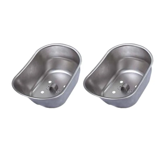
Three cavities in one part means the metal has to move in six directions
A custom triple-cavity deep drawn aluminium shell is not three small features – it is one part where the sheet metal has to be divided and pulled into three separate pockets in a single sequence. That is a fundamentally harder forming problem than a single-cavity shell, and almost every difficulty on this part comes from the fact that the material at the boundary between two cavities is being asked to do two incompatible things at once.
We run these as multi-stage deep draws with interstage annealing, trimmed and pierced in following dies, with in-process checks between stages rather than only at the end. Press shop runs 5-250 T mechanical and 250-500 T hydraulic presses with annealing ovens on site, in-house toolmaking keeping dies and fixtures maintained. Turned secondary features to +/-0.03 mm and as-drawn walls to +/-0.1 mm, with finer bands confirmed from capability data before quoting. Zinc, nickel or chrome plating, anodising, passivation or e-coat, and the agreed finish travels with the part number. This page is about what a multi-cavity draw does to material, and where the design decisions are.
The core problem: the wall between two cavities
Imagine a flat blank with three circles drawn on it and a flat area between them. The metal in that flat area has to become the wall of cavity one, then the wall of cavity two, and the two walls meet at a ridge. The metal at that ridge has been stretched in one direction to form one wall and in a different direction to form the other, and the corner where they meet is where the material is most stretched and most stressed.
Three practical consequences on the drawn part:
- The wall between cavities is thinner than the walls at the cavities’ outer edges. Material flows into the cavities’ bottoms, so it thins there; between them it is stretched in two directions rather than drawn into. The minimum wall on a multi-cavity part is usually at the inter-cavity ridge, and the drawing’s wall tolerance needs to apply there.
- The inter-cavity ridge is where cracking starts. Because it is the most stretched and the most highly stressed region, and because it carries a stress concentration from the change in direction, it is where a multi-stage draw will split if the radii are too tight. The punch and die radii at that ridge should be the most generous on the part.
- Cavity-to-cavity alignment is a dimensional requirement, not just a forming one. If two cavities must carry features that interact – a valve in one and a seat in the other, for example – the relationship between those features has to be controlled, and it is controlled by the flat blank’s geometry, not by the drawing operations. So it is a feed-and-pilot accuracy requirement.
Draw sequence: one cavity is always first
A multi-cavity draw is staged, and the sequence follows a logic that is worth understanding because it explains the part’s final shape:
- The first cavity is the largest or the deepest. It is drawn first because it needs the most material flow and the most ductility, and starting with a smaller cavity would leave the material in a worse condition for the next one.
- The second cavity draws into material that has already been worked, so its forming limit is lower and its thinning is higher. This is why interstage annealing is on the route for this part – not as an optional step but as the thing that makes the later cavities possible.
- The last cavity is formed with the least material available. It is usually the smallest and shallowest, and it is where the process is most constrained.
- Trim and pierce happen in the following dies, once the part’s shape is essentially final. Piercing after the cavities are formed means the holes are located on a formed part – so any hole that must be precisely located should be pierced in an earlier stage or, better, in the flat.
Blank design: the flat between the cavities
The blank’s layout is the design’s real control, and three features of it decide the whole part’s viability:
- The web between adjacent cavities. The flat material separating two cavities. Too wide and the cavities cannot be drawn far enough; too narrow and the material between them is stretched beyond its limit and the ridge cracks. The web’s width is therefore a functional dimension with both an upper and a lower bound, and it should be specified.
- The blank’s diameter relative to the cavity layout. A larger blank relative to the cavities means more material is available and the draw is easier, but more material is wasted. The optimum is a balance and it is the kind of thing the manufacturability review is best placed to judge.
- The overall blank’s eccentricity. If the three cavities are not symmetrically arranged around the blank’s centre, the material’s flow is asymmetric and the part’s dimensional repeatability suffers. Where the cavities’ arrangement allows a symmetric blank, this is preferable and worth asking about at review.
Aluminium, and its specific behaviour in this process
SPCC and DC01 cold-rolled carbon steel in 0.5-3.0 mm is the standard stock for a formed component, with pickled or galvanised alternatives – and aluminium is the material named on this part. The reasons and the demands:
- Formability is excellent, which is why a multi-cavity draw in aluminium is more achievable than the same geometry in steel. Aluminium’s lower yield strength means less force is needed and the material tolerates a larger stretch before failing.
- It work-hardens fast, which is why interstage annealing matters more here than in a steel draw. Without it, the third cavity is being formed from material that has been stretched twice already and it will crack or thin badly.
- The oxide skin is a real consideration, both in forming and in finishing. During the draw, retained lubricant under the oxide is a corrosion site. In finishing, an annealed surface carries an oxide that has to be cleaned before anodising or plating – and on a complex three-cavity geometry, cleaning is harder because the cavities hold lubricant and cleaning fluid.
- The final geometry will spring back more than steel, and on a complex shape this affects the repeatability of the cavity shapes. This is the honest limitation on a tight tolerance across a compound form and it should be established from capability data before quoting rather than assumed.
Finishing a three-cavity part
Zinc, nickel or chrome plating, anodising, passivation or e-coat, with the agreed finish travelling with the part number. On this geometry the finishing choices are constrained by the cavities:
- Coverage inside the cavities is the limiting factor for any coating. Plating solution and rinse have to reach the cavity bottoms, and on a deep, narrow cavity the coverage there will be thinner than on the outer surfaces. Anodising does this better because it is a surface conversion rather than a deposited layer, and it grows slightly outward uniformly.
- Plating growth closes the cavity openings. A cavity whose mouth is a fitted dimension – a port, a sealing face, an assembly interface – will change by roughly twice the plating thickness at its opening. This must be specified as before or after plating.
- Anodising suits this part well for exactly the cavity reason: uniform layer growth, good coverage by comparison with plating, hard surface, and no dimension bridging problems at the mouths.
- Passivation or a bare cleaned surface is the right choice where no dimensional change is wanted, and on an aluminium part it will not give the corrosion protection that anodising does.
Six things, ordered by how much they change the design
Six things, in rough order of how much they change the design:
- The web width between cavities, with both limits understood. This is the dimension that determines whether the part is drawable at all.
- Which cavity is which – the sequence is not arbitrary, and if the design has assumed the deepest cavity can be drawn last, that is worth discussing.
- Minimum wall thickness, stated at the inter-cavity ridge rather than at the cavity walls, because that is the thinnest point.
- Which features must be aligned to which, and to what tolerance – this is a blank-geometry requirement, not a die operation.
- Which holes are pierced in the flat versus after forming, and the position tolerance for each.
- Whether dimensions apply before or after finish, on every cavity mouth and port.
And the question worth asking at review: does this part need to be three cavities in one piece. Three separate parts assembled can be cheaper, easier to make and easier to inspect than one three-cavity draw – and on a part where the cavities’ alignment is not functionally important, splitting them removes the entire inter-cavity ridge problem. It is worth having that conversation before the die is cut, because splitting a part after the design is fixed is expensive and splitting it before is nearly free.
If you are weighing drawing against machining or welding for this geometry, the guide to deep drawn covers sets out where each route wins; the full Precision Deep Drawn Parts range is linked from the overview page.
Specifications
| Item | Custom Triple-Cavity Deep Drawn Aluminum Shell |
|---|---|
| Brand | AUNOV |
| Designing | Quotation is built from the drawing: DFM notes come back with the price rather than after tooling. |
| Tooling | Progressive and forming dies are designed, built and maintained on site. |
| Samples | Sample parts are measured and reported before submission, so any deviation is corrected at sample stage. |
| Materials | SPCC / DC01 cold-rolled carbon steel, 0.5-3.0 mm, the standard stock for formed component; pickled (SPHC) or galvanised alternatives. |
| Surface finish | Zinc, nickel or chrome plating, anodising, passivation or e-coat; the agreed finish travels with the part number. |
| Processing | Multi-stage deep drawing with interstage annealing, trimmed and pierced in following dies; in-process checks sit between stages, not only at the end. |
| Equipment | Press shop running 5-250 T mechanical and 250-500 T hydraulic presses, annealing ovens on site, with in-house toolmaking to keep dies and fixtures maintained. |
| Tolerance | +/-0.03 mm on turned secondary features, +/-0.1 mm on as-drawn walls; finer bands confirmed from capability data before quoting. |
| Delivery terms | Freight is quoted to your door in FOB, CIF or DDP terms, payment by T/T or L/C. |
Frequently Asked Questions
Why is a three-cavity shell harder than three separate single-cavity shells?
It is one part where the metal has to be divided and pulled into three pockets in a single sequence, which means the material flow has to be balanced in both directions at once. Nearly every difficulty on this part comes from that boundary material being asked to do two incompatible things simultaneously.
Which single feature decides the design?
The wall between two cavities. Those pockets compete for the same metal, and if the intervening section thins below what the next stage needs, the shell fails at the boundary rather than at either cavity. It is the first thing settled in blank development, not something checked after the fact.
Can all three cavities be drawn at the same time?
In practice one cavity leads and the others follow in sequence, because simultaneous forming gives no way to feed the boundary material predictably. The multi-stage draw, with interstage annealing and in-process checks between stages rather than only at the end, is what keeps wall distribution under control.
Why is annealing written into the stage plan instead of added if needed?
The stage count is the tooling cost, so it belongs in a priced plan that is quoted openly rather than discovered mid-run. When a geometry needs staged drawing with annealing, deep enough draws beyond the first reduction are routine on hydraulic presses up to 500 T, and treating that as an unplanned rescue is what makes a multi-cavity part expensive late in the project.
Related Products


Request a Quote for This Part
Send a drawing or sketch — get material advice, tooling cost and a per-piece price within 24 hours (working days).