
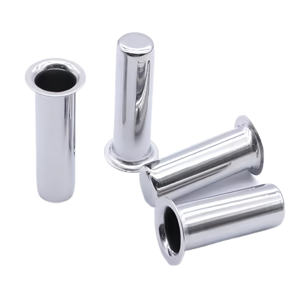
Hard chrome or decorative chrome: two coatings that share a name
“Chrome plated tube sleeve” appears on thousands of drawings, and most of them do not say which chrome they mean. The two candidates are industrial hard chrome – typically 10-100 micrometres of dense, as-deposited chromium applied for wear resistance – and decorative chrome, a sub-micron bright layer over nickel and copper that exists to look right and stop tarnish. They share an element and almost nothing else, and on a flanged tube sleeve the difference decides whether the part survives ten thousand insertion cycles or ten.
A flanged sleeve in the work we see is usually one of two things: a wear bushing that something slides or rotates in – a guide sleeve, a pushrod guide, a shock absorber eye – or a cosmetic-functional part where the sleeve is visible and the chrome is doing corrosion and appearance duty on a stamped or drawn body. The material logic follows:
- Wear service means hard chrome over a drawn steel sleeve, usually SPCC/DC01 or a 1045-type carbon steel for its response to the bath. The chrome is the bearing surface, typically 20-40 micrometres after grind, honed or as-plated depending on the fit class.
- Decorative service usually means a drawn carbon-steel sleeve with copper-nickel-chrome, where the chrome is under a micron and the corrosion protection is actually the nickel. This is the finish of a visible appliance or furniture part, and its acceptance criteria are visual, not dimensional.
- Thin hard chrome, 8-15 micrometres as-plated, is the compromise on sleeves with moderate wear duty where grinding after plating is not wanted – it can be plated close to size on a drawn sleeve with the growth allowed for on the drawing.
Chrome grows on the sleeve: post-plate dimensions on a slip fit
Chrome deposits outward from the base surface, and on a sleeve it grows in two directions at once: the OD grows by roughly twice the thickness per side, and the bore shrinks by the same amount. That is arithmetically trivial and procedurally easy to get wrong, because the question it raises – are the drawing dimensions pre-plate or post-plate – is answered on far fewer drawings than it appears on.
Consider a plain sleeve, OD 12.00 mm, bore 8.00 mm, both called at H7/f-style fits, plated 20 micrometres hard chrome as-plated. If the drawing dimensions are pre-plate, the machined sleeve is drawn at 12.00 and the plated part measures about 12.04 on the OD and about 7.96 in the bore – a 40-micrometre interference growth on a fit that probably had 25 micrometres of clearance in it. The part does not assemble, and it does not assemble in a way that looks like anyone’s fault on the shop floor, because every pre-plate dimension was in tolerance.
Our practice on plated flanged sleeves is to dimension the functional surfaces post-plate and state it, with a plating allowance applied in the drawing operation:
- Functional bore and OD dimensioned post-plate – these are what the mating parts see, so these are what we verify and what the report certifies.
- Non-functional surfaces left pre-plate – flange faces, outline dims, cosmetic surfaces – which keeps the verification list short and honest.
- Plating thickness and distribution stated per surface, because chrome throws unevenly: the OD of a tube plates close to nominal thickness, the bore plates thinner – typically 60-80 percent of the bath nominal on a sleeve-bore aspect ratio – and the flange-to-wall fillet is thinner again.
- Where the fit is critical, the bore is machined after plating. A honed or bored post-plate chrome bore is flat, round and within a couple of micrometres, and on a genuine precision fit it is cheaper than scrapping the percentage of an as-plated batch that misses.
The flange is the datum, and the plating is thinnest behind it
A flanged sleeve is almost always located by its flange: the flange face seats against a housing shoulder, the flange OD or its bolt pattern registers the sleeve, and everything else hangs off that seat. That makes the flange the datum, and it collides with an electroplating fact – the flange-to-barrel fillet is one of the lowest-current-density zones on the whole part. Chrome follows the electric field, and the field is weak in the shadowed corner where the flange meets the wall. A sleeve plated at 20 micrometres on the barrel OD can measure 10-12 micrometres in the fillet, and a bare or thin-chrome fillet on a carbon-steel sleeve in any humid environment is a ring of rust that starts growing exactly at the part’s datum.
The remedies are design-level, not plating-willpower-level:
- Generous fillet at the flange root. A 1.0-1.5 mm fillet draws current into the corner and gives the deposit somewhere to land. A sharp root guarantees a thin zone no matter how the bath is racked.
- State a minimum thickness for the fillet zone, or agree that the fillet is corrosion-protected by the nickel underlayer rather than the chrome. On a decorative copper-nickel-chrome stack, the nickel is the corrosion layer anyway, and a stated minimum nickel in the fillet is a more honest specification than chrome everywhere.
- Consider the flange face masked. If the flange face is a seating datum, chrome on it is a thickness-growth problem and a friction problem; masked bare steel or a masked face ground after plating is often the better call, and the drawing should say so.
- Rack orientation agreed. We rack sleeves flange-up or flange-down per part, with conforming anodes where the bore plating matters, and the racking is part of the process record so a reorder plates the same way.
Drawing the sleeve so the plating bath can reach the bore
A sleeve is a deep, narrow cavity, and plating a bore is an electrochemistry problem before it is a bath-time problem. Current and fresh electrolyte have to reach down the bore’s length, and throwing power – the bath’s ability to plate low-current-density zones – is finite. On a bore with length-to-diameter ratio above about 3:1, the deposit at mid-bore drops measurably below the ends; above 6:1, uniform bore plating needs conforming anodes (a centred internal anode that follows the bore) or it does not happen at all.
What that means for the drawing, in practical terms:
- Sleeves with bore L/D under 3 plate acceptably in a conventional bath with good racking, and we quote them as standard, with the bore at 60-80 percent of the nominal thickness called out on the process sheet.
- Bore L/D 3 to 6 gets a stated bore minimum and slightly longer bath residence, and if the bore is functional-wear the quotation will offer post-plate honing, because a uniform honed chrome bore beats a uniform-enough plated one.
- Bore L/D over 6 – a long guide sleeve – is either a conforming-anode job or a masked-bore job, and the honest engineering answer is frequently the masked one: plate the OD, leave the bore bare steel and machine it, or specify a different bore strategy entirely. We will say so at review rather than accept a spec the bath cannot meet.
- Hydrogen is generated at the part surface during plating. On a cold-drawn sleeve – and drawn sleeves carry heavy cold work – the plating step charges the steel with hydrogen, and the mitigation is a post-plate bake at around 200 degrees C within a defined window after removal from the bath. Our standard for sleeves in any load-bearing or fatigue service is a 4-hour bake within 2 hours of plating, stated on the process traveler and on the certificate.
Hydrogen management on a cold-drawn sleeve
Taking the hydrogen argument one step further, because a cold-drawn sleeve concentrates three hydrogen risks in one part. First, the drawing process itself: heavy cold work creates a heavily dislocated microstructure that soaks up hydrogen from cleaning acids and from the plating bath faster and holds it longer than annealed steel. Second, the pre-plate cleaning: acid activation is standard before chrome, and it is an immersion-hydrogen event. Third, the chrome bath itself, which is the least efficient of the common baths and therefore generates the most hydrogen at the part surface per ampere-minute of plating.
The risk ladder is well established in fastener and tubing practice and applies directly here:
- Sleeves from soft, low-carbon steel (SPCC/DC01, lightly drawn) are at the bottom of the ladder. The bake is still good practice, but the embrittlement risk in a soft ductile steel is modest, and a 4-hour bake is abundant.
- Heavily drawn thin-wall sleeves are mid-ladder – enough cold work to matter, enough section to keep it forgiving. We bake these as standard, and we prefer schedules with an intermediate anneal so the finished sleeve carries moderate cold work rather than maximum.
- Any sleeve in high-strength steel or with a hardness above roughly 34 HRC is top of the ladder: hydrogen embrittlement failure is a live risk, the bake window is a hard requirement (typically within 1 hour, 8+ hours at temperature), and we would rather quote that part with an engineering conversation than a catalogue line.
How we verify a plated flanged sleeve against its drawing
Verification on a chrome-plated flanged sleeve runs in two stages – before plate and after – because a plated part can only be verified honestly when the two stages are separate:
- Pre-plate dimensional check on the machined/drawn sleeve: OD, bore, flange OD and thickness, flange squareness and the fillet radius, against the pre-plate drawing with plating allowances applied. Anything wrong here is found while it is still fixable.
- Thickness verification after plating: magnetic-induction or XRF thickness measurement on the barrel OD, the flange face, the flange OD and – where the drawing requires bore plating – in the bore at entry, mid-length and far end. We report the distribution, not just the nominal, and the fillet-zone minimum is reported against its stated minimum.
- Post-plate dimensional verification on the functional features dimensioned after plate: the bore by plug or air gauge, the OD by micrometer, with gauge force stated.
- Adhesion: a bend-and-observe or burnish test on samples from every lot, plus the standard requirement that there is no blistering, flaking or peeling at the fillet or the flange edge after a sharp impact on samples.
- Hydrogen embrittlement verification where specified: sustained-load proof loading on samples held at a defined percentage of proof strength for a defined duration, or simply the bake record audited against the traveler, per the drawing’s stated requirement.
- Appearance against an agreed limit sample for decorative work – chrome shows everything, and “bright” needs a physical reference, not an adjective.
- Material and plating certificates with the shipment: the base steel’s mill certificate, the plating process record including thickness readings and bake times, and the dimensional report on the post-plate features.
Send drawings or a sample to be measured. The manufacturability review that comes back with the quotation will state which chrome is assumed, which dimensions are pre- and post-plate, the bore plating reality at your sleeve’s length-to-diameter, the fillet thickness minimum we will commit to, and the bake window – so the part that ships is the part the drawing meant.
Deep Drawn Tubes & Sleeves is the parent range for parts like this one; the overview page gathers the tooling logic, finishing options and tolerance notes that apply across the family.
Specifications
| Item | Chrome Plated Precision Flanged Tube Sleeves |
|---|---|
| Brand | AUNOV |
| Designing | A drawing file or a physical sample starts the review, you get a DFM review together with the quotation. |
| Tooling | Our own toolroom designs and builds every die, each die held against your part number. |
| Samples | Sample parts arrive with a full dimensional report and mill certificate. |
| Materials | Stock covers carbon steel (SPCC / DC01), 304 / 316 stainless steel, aluminium, brass and copper, per the drawing. |
| Surface finish | Surface treatment per the drawing: plating, e-coat, powder coating, anodising, passivation, per the drawing. |
| Processing | Staged deep drawing, with in-line annealing where the draw ratio requires, pierced and finish-machined on the same floor. |
| Equipment | Our press floor runs 5-250 T mechanical and 250-500 T hydraulic presses, in-house CNC cells and a temperature-controlled inspection room. |
| Tolerance | +/-0.1 mm as-drawn, +/-0.03 mm after machining. |
| Delivery terms | FOB standard, DDP offered for EU and US, payment T/T or L/C, D/P for repeat accounts, call-off schedules and blanket orders supported. |
Related Products


Request a Quote for This Part
Send a drawing or sketch — get material advice, tooling cost and a per-piece price within 24 hours (working days).