
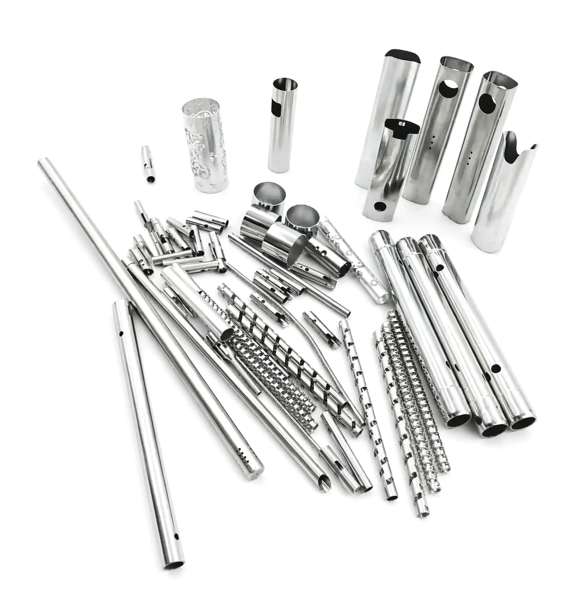
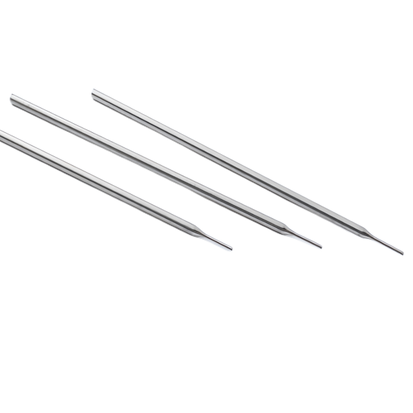
A 304 precision capillary with a variable diameter is a tube that has to do two jobs that fight each other: carry a fluid or a fill precisely, and change diameter so that it can connect to something. The variable diameter is a connector feature, and connectors introduce features that disturb flow and introduce steps that disturb thermal behaviour. So on this part the design question is where the diameter changes go relative to what the tube is carrying.
Tube drawing, straightening and turning in one flow, on drawing benches with in-line annealing, at +/-0.02 mm on turned diameters with the wall held to an agreed band and capability checked on the first article. So the tight band is on the machined ends and the wall is banded by agreement – and on a variable-diameter capillary that is the correct shape of specification, because the ends are what connect and the wall is what carries.
Where the diameter changes, and why the position matters
- A diameter change is a metal-flow event, and in a drawn tube a reduction thins the wall at the transition. So a transition on a pressure or fill line is the thinnest section of the line and it needs to be stated and checked there.
- An increase cannot gather metal the way a solid can, so a larger-diameter section on a smaller tube is a built-up joint – a sleeve brazed, soldered or welded on. Which means a variable-diameter capillary in the expanding direction has a joint in it, and the joint’s leak performance and its thermal resistance are both part of the part.
- And the position of the transition relative to the working length is a design decision. A transition placed close to the sensing or delivery end is in the active path and adds a pressure drop and a disturbance. A transition placed back in the cold, mechanical end is out of the way. Where it goes matters more than its geometry.
So the first question on this part is: what is the tube carrying, and which end of it is active? Because the transition belongs in the mechanical end unless there is a reason for it not to, and the reason is usually that the connector has to be there.
The wall, banded by agreement, and why
The wall held to an agreed band with capability checked on the first article is an honest way to specify a drawn tube’s wall, and on this part it is doing more work than usual.
- The wall’s variation along a drawn tube comes from the material and the draw, and on a variable-diameter tube the variation compounds at each transition. So a nominal wall with a general band would hide the fact that the wall is not the same at every diameter.
- Where the tube carries a fluid, the wall is the pressure boundary and its minimum at the transition is the number that decides whether the part holds. Where it carries a fill in a temperature system, the wall is also the thermal path and its uniformity decides the accuracy.
- So the wall should be stated at named locations – each section and each transition – with a minimum where the minimum matters. And on a first article the wall’s uniformity along the length should be measured, because a wall that varies is a part whose behaviour varies with position.
The turned diameters, and why they carry the tight band
At +/-0.02 mm the ends carry the precision, and on a capillary that is correct for a reason that is worth stating plainly.
- The ends are what seal, connect, or thread. They are finish-turned after the draw, so the machine holds them, and a connection’s leak performance is set by them.
- And on a variable-diameter tube the end diameters’ concentricity to each other matters more than their individual sizes, because the assembly’s behaviour depends on the sections being coaxial – a transition that is eccentric relative to the tube’s axis produces a flow disturbance that is not symmetric and a thermal error that is not either.
- Where the end is a seal rather than a connector – a closure, or an interference in a fitting – its size is a fit and the same tight band applies.
Straightness, and the flexibility question
- A drawn capillary carries residual curvature and it is straightened, and on a variable-diameter part the straightening works on the uniform sections and not on the transitions, so the transitions’ positions relative to the ends are what straightening cannot improve.
- And a variable-diameter tube is stiffer than a straight one of the same length, because the larger sections contribute more bending stiffness. So a design that specified a straight tube for flexibility and then added a larger section for connection has made it less flexible, and if the routing depends on flexibility that is a conflict worth resolving before the drawing is issued.
- The minimum bend radius, scaled by the wall rather than the diameter, and on this part with its transitions the smallest-wall section governs the whole part’s bendability. So the variable-diameter feature may set the routing requirement for the entire tube.
On a capillary, the grade question is the chloride question
Stock runs to carbon steel, 304 / 316 stainless steel, aluminium and brass, with the final grade fixed at the drawing review. Three points where a capillary’s material choice has a specific consequence.
- 304 versus 316L is the chloride question, and on a capillary that may be cleaned or may carry a mildly aggressive fluid it is the usual deciding factor. Where the part is a temperature-sensing element in a clean application, 304 is usually the right answer.
- Residual stress and corrosion. A drawn and straightened capillary carries residual stress from both operations, and in a chloride-bearing environment that is a stress-corrosion cracking risk. The delivery condition is therefore a durability specification and not a forming detail.
- And a built-up transition introduces a second material. A brazed sleeve on a 304 tube uses a copper or brass filler, and that filler is in contact with whatever the tube carries. On a temperature-sensing application it is a junction in the gradient; on a fill line it is a dissimilar metal in a wetted path. So where the tube is expanded, the filler’s identity is a specification and not an internal detail.
The first two items here are what cause field problems if missed
Plating, coating or polishing per the print, with the finish inspected with the dimensional report on the first article. Three items, and on this part the first two are the ones that will cause field problems if missed.
- Fitted diameters and sealing faces, unmasked.
- On stainless steel, passivation rather than plating – and where a brazed transition is present, passivation must follow the brazing because brazing removes the passive film over a larger area than machining does.
- The interior, where the tube carries a fill or a sample – cleanliness is functional, and on a drawn tube the interior’s surface at the transitions carries forming residue and is a deposition site.
Concentricity between the turned diameters is the relationship that matters
+/-0.02 mm on turned diameters with the wall held to the agreed band. Four items and the fourth is the accuracy.
- Turned diameters: size, roundness, and concentricity to each other at the tight band, with the concentricity as the more important of the relationships on a variable-diameter part.
- Each transition’s geometry and length, at a band that reflects springback and, on a built-up section, the fit of the sleeve.
- The wall at each section and each transition, with a minimum at the thinnest.
- And the requirements that are not dimensions: the minimum bend radius, the leak rate along the length, the interior’s cleanliness, and the insertion depth if the tube is a sensing element. On a variable-diameter capillary the first three decide whether it functions and the fourth decides whether it is accurate, and none of them is a tolerance.
Wall thickness at every transition is where a hex-top sleeve fails
Capability is checked on the first article before the run continues. On this part the inspection has to look at both the ends and the flow path.
- Turned diameters at the tight band, including concentricity between them.
- Wall thickness at every section and transition, with the minimum compared against its figure and the uniformity along the length measured on the first article.
- Straightness and the transitions’ positions, after straightening.
- And a functional leak test along the length where the tube carries fill or process fluid. An end test on a capillary with a built-up transition proves nothing about the transition, which is exactly where it will leak.
Does the diameter have to change, or can the connection be made otherwise?
Does the diameter have to change at all, or could the connection be made another way? It sounds like a small question and on this part it can remove several problems at once. A variable-diameter capillary carries a transition, and the transition is a thinning section, or a joint, or both – and each of those is a potential leak path, a pressure drop, a thermal discontinuity, and a place where the drawing’s tolerance scheme has to split. Where the connection could instead be made by a fitting, a swaged end, or a different end form on the same diameter, the variable-diameter part becomes simpler in the drawing, more consistent in production, and better thermally. And where the variable diameter genuinely is necessary, the second question is: which end does it have to be on? Because placing the transition in the mechanical end rather than the working end takes it out of the flow path and out of the temperature gradient, and on a part like this that is a free improvement that costs nothing but a decision made before the tooling exists.
This part belongs to our Deep Drawn Tubes & Sleeves range. The deep drawn tubes & sleeves pages collect the process notes, common materials and inspection points behind every product in the family.
Where this part is used
A capillary that changes diameter is usually not a single-purpose part. It is the transition between a sensing or dispensing element and the rest of the system, and that means it lives in two worlds at once: the section that carries fluid or fill, and the section that has to mate with a fitting. You will find these in thermal-mass flow controllers, in gas analyzers, in dispensing valves for adhesives and solvents, and in sampling lines where a very small volume has to move a long way.
Because the transition is the connector, the diameter change is normally placed where the connection is, and the rest of the tube stays a single diameter for as long as possible. When the two requirements collide – a tight pressure line that also needs to reach a fitting of a different size – the part is built up rather than drawn down, and that joint becomes the feature that decides the leak performance of the whole assembly.
What we need to quote it
Tell us what the tube carries and which end is active, because that determines where the transition belongs. Give us each diameter with its tolerance, the wall you want held on each section, and whether the larger section is drawn up or built up onto the smaller one. If it carries gas or a liquid that must stay clean, say so – the material grade and the internal finish both follow from that. The length between the transition and the working end matters as much as the geometry.
Specifications
| Item | 304 precision stainless steel capillary variable diameter tube |
|---|---|
| Brand | AUNOV |
| Designing | Send drawings, or send a sample to be measured – DFM notes are returned before any tooling is cut; the agreed version governs every later batch. |
| Tooling | Progressive and drawing dies are designed and built in house, so the die charge appears as its own quotation line, and ownership is confirmed on the quotation. |
| Samples | Sample parts are measured and reported before submission, so any deviation is corrected at sample stage. |
| Materials | Stock runs to carbon steel, 304 / 316 stainless steel, aluminium and brass; the final grade is fixed with the drawing review. |
| Surface finish | Plating, coating or polishing to suit the drawing; the finish is inspected with the dimensional report on the first article. |
| Processing | Tube drawing, straightening and turning in one flow; every stage is logged against your part number. |
| Equipment | Tube drawing benches with in-line annealing furnaces, backed by CNC turning centres and a climate-controlled inspection room. |
| Tolerance | +/-0.02 mm on turned diameters, wall held to the agreed band; capability is checked on the first article before the run continues. |
| Delivery terms | Standard terms FOB; DDP available for EU and US, with T/T and L/C accepted. |
Related Products



Request a Quote for This Part
Send a drawing or sketch — get material advice, tooling cost and a per-piece price within 24 hours (working days).