
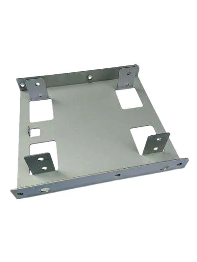
A bracket is a tolerance problem that happens to be made of sheet metal
Progressive die stamping makes a precision bent bracket cheaply and repeatably, and it does so by turning a flat strip into a three-dimensional part inside a single stroke: pierce, bend, bend again, trim, and eject a finished bracket. Every one of those stations introduces a small error, and the bracket that goes into service is the sum of all of them. This page looks at where those errors come from and how a drawing gets written so the errors land on features nobody cares about.
We run progressive die stamping with trimming and forming in one pass, trim and form to the print, and hold +/-0.05 mm on bend positions and +/-0.1 mm on blank outline. Where a dimension needs to be tighter than that, we say so up front and confirm it from capability data before quoting rather than after the first article arrives.
Stations add up: the error budget of a four-bend bracket
Think about a bracket with four bends, a pierced hole pattern and a trimmed outline. In a progressive tool the material passes through stations in a fixed order, and the part’s accuracy is the accumulation of:
- Blank outline position. Set by the coil feed pitch and the pilot. This establishes the part’s own datum and contributes directly to every downstream position.
- Pierce position. Piercing happens in the flat, where accuracy is best. This is why holes pierced before forming are more accurate than holes formed in the same station as a bend.
- Bend location along the length. Each bend is placed by the shut height of its punch, so bend position error is a function of the press’s own repeatability and the punch’s wear.
- Bend angle. Set by the V-die and the punch nose radius, minus springback. This is where material thickness variation turns into angle variation.
- Twist and sidewall bow. Forming asymmetric sections introduces out-of-plane distortion that no single dimension captures.
The engineering conclusion is not mysterious but it is often ignored: do the accuracy-critical operations while the part is still flat. Hole position, slots, cutouts and embossed datums are all cheaper to hold in the flat blank than after the part has a shape. If a drawing shows a tolerance of a few hundredths on a hole that is formed after the bracket has been bent twice, the sensible conversation is about moving the hole upstream – which usually costs nothing at all in tooling.
Springback, and why the same die does not give the same angle all day
Sheet metal that is bent past its elastic limit does not return exactly to the shape the tool made. The recovery is springback, and it depends on four things:
- Yield strength and modulus of the specific coil. High-strength steel springs back more than mild steel. The number that matters comes from the mill certificate for the actual coil being run, not from a handbook average.
- Bend radius relative to thickness. A tight bend radius raises the through-thickness stress and therefore the springback, and also opens the risk of outer-surface cracking on high-strength grades. The rule of thumb that the inside radius should be at least one thickness is a cracking rule; a radius of two to three thicknesses buys much better bendability and much more stable angles.
- Thickness variation across the coil. This is the sleeper. Angle is sensitive to thickness, so a coil running at its thin edge gives a different angle from the same coil running at its thick edge, and a bracket that meets its angle tolerance on the first half of the coil fails on the second.
- Grain direction. Bending transverse to the grain is consistently harder and gives less stable angles than bending along it. The grain direction of a rolled sheet is a real drawing requirement on a precision bracket, and it is worth stating as rolling direction rather than leaving it to the producer.
On the shop floor this shows up as a bracket that is out of angle but gets tooled back. The correct response is to record the actual thickness band of the coil, calculate springback for the mean of that band, and adjust the tooling once – not to chase parts with hand shims. We check first articles and batch samples on the CMM, so the first article should be measured against the coil that will actually be run, not against a nicer sample.
Flatness, and why vibratory finishing is a metrology event
A bracket is very often a mounting part, which means something has to sit flat on it. Stamping does not guarantee flatness, and the two things that destroy it are:
- Residual stress from forming. A bend leaves the inner fibre in compression and the outer in tension, and a thin bracket with several bends can bow when those stresses find relief.
- Handling and burr condition. Sharp burrs on a thin bracket are where it gets picked up, dropped, or bent in the bin. A burr that is too aggressive also acts as a stress raiser.
Vibratory finishing lines – which we run in-house – do two useful things here: they take the edge down to a consistent, specified burr height, and they relieve enough of the surface to noticeably drop the residual stress. Both effects improve flatness and both improve fatigue life. The point worth making is that the finishing spec should be written deliberately. A named burr height and a named Ra are more useful than the phrase deburred, because deburred does not describe a measurable condition and a bracket with an uncontrolled burr is a bracket with an uncontrolled fatigue life.
Distortion control: what the drawing can actually do
Most precision brackets need some combination of these four measures, and each one costs something, which is why the drawing review should decide them deliberately rather than leaving them to the toolroom:
| Pierce while flat | Moves hole position error upstream to where it is smallest. Costs nothing. Should be the default. |
|---|---|
| Bend relief / relief slots | A small cutout at the inside corner of a bend where two flanges meet. Removes the material that would otherwise be in tension at the corner, and is the standard fix for a cracked or distorted corner. |
| Dowels or beads near a bend | Constrain springback at the bend and lock in hole position after forming. Adds a station, so it is worth it where the hole matters and not worth it where it does not. |
| Sizing / coining station | A final light press that brings bend angle and thickness into a narrow band at the expense of tool life. Reserved for brackets whose angle tolerance is genuinely tight. |
The complementary measure is in inspection: measuring a bracket while it is clamped flat hides the very flatness error you want to find. The honest procedure is to measure free-state flatness across the mounting face with a feeler or a height gauge, and to report it as such.
Materials: the choice changes the tool, not just the look
Carbon steel in SPCC and DC01 grades covers the majority of precision brackets and is the most forgiving material to form. Aluminium forms at lower tonnage and springs back differently, and while it does not rust it does have a surface that matters – and a bracket in aluminium usually wants anodising or coating for appearance and for edge protection. 304 and 316 stainless steel are the corrosion answer and the hardest to form; expect higher tonnage, more springback, and a wear rate on the tooling that should be built into the die’s expected life rather than discovered.
Brass and copper appear where conductivity matters or where the part is a small precision component; both are relatively easy to form and both have their own surface handling requirements.
Surface treatment is plating, coating or polishing to suit the drawing, with masking and laser marking available where needed. Masking is worth specifying explicitly for a bracket: a plated mounting face that has to be masked is a different cost and a different lead time from a bracket plated all over, and it is much better to find that out at quotation.
Files, tooling and what to expect commercially
Files come in as PDF, DWG, STEP or IGS and are reviewed before the die is cut; the signed-off revision is the reference for production. Tooling is built and held under your part number, so the die charge appears as its own quotation line and the first-article clock starts from the tooling start date rather than from the day the order arrived. Pre-production samples come with a full inspection report, and the approved first article becomes the gauge reference, with the signed sample kept for future reorders.
Delivery is FOB, CIF or DDP per Incoterms 2020, payment by T/T, L/C at sight or D/P, with price breaks tied to annual volume – which is the natural shape for a progressive die part, because the die cost is front-loaded and the piece price amortises.
The three questions that most improve a precision bracket drawing, in order: which dimensions are genuinely critical to the assembly and which are inherited from a general tolerance, which hole must be located and everything else can float, and what the bracket has to sit flat against. Answer those three and most of the tolerance scheme writes itself.
Custom Metal Stamping Parts is the parent range for parts like this one; the overview page gathers the tooling logic, finishing options and tolerance notes that apply across the family.
Where this part is used
A precision stamped and bent bracket is the shape most often described as simple and most often specified poorly. It is made in a single stroke on a progressive die – pierce, bend, bend again, trim, eject – and every one of those stations adds a small error. The part that reaches the assembly is the sum of all of them, and the useful skill is writing the drawing so that those errors land on features nobody cares about.
You will find these brackets in machinery, in control cabinets, in mounting plates, in equipment frames and in the brackets that tie a motor to a machine bed. They are specified by people who want a specific bend, a specific hole and a specific flatness, and who have not necessarily thought about which of those features actually carries load. Getting that ordering right on the drawing is worth more than any tolerance discussion afterwards.
What we need to quote it
Send the drawing with the bends in the order you want them produced and the tolerance that matters marked. Give us the material grade and the thickness – they determine the tool, not just the appearance. Tell us whether the part must stay flat, because flatness is affected by how the part is handled and finished, not only by how it is formed. If the part has to be plated afterwards, say which features need masking, because masking is a tooling decision taken at design time.
Specifications
| Item | Precision Stamped and Bent Bracket |
|---|---|
| Brand | AUNOV |
| Designing | Files reviewed in PDF, DWG, STEP or IGS; the signed-off revision is the reference for production. |
| Tooling | Tooling is built and held under your part number, so the die charge appears as its own quotation line, and first-article timing is measured from the tooling start date. |
| Samples | Pre-production samples come with a full inspection report, so the approved first article becomes the gauge reference, and the signed sample is kept for future reorders. |
| Materials | Carbon steel (SPCC / DC01), 304 / 316 stainless steel, aluminium, brass and copper – the grade is matched to the duty of this bracket. |
| Surface finish | Plating, coating or polishing to suit the drawing; masking and laser marking available where needed. |
| Processing | Progressive die stamping, trimmed and formed in one pass; first articles verify the whole flow before the run is released. |
| Equipment | Mechanical presses 5-250 T, decoilers and coil feeders, vibratory finishing lines and a full in-house toolroom. |
| Tolerance | +/-0.05 mm on bend positions, +/-0.1 mm on blank outline; finer bands confirmed from capability data before quoting. |
| Delivery terms | FOB, CIF or DDP per Incoterms 2020, payment by T/T, L/C at sight or D/P; price breaks tie to annual volume. |
Related Products



Request a Quote for This Part
Send a drawing or sketch — get material advice, tooling cost and a per-piece price within 24 hours (working days).