
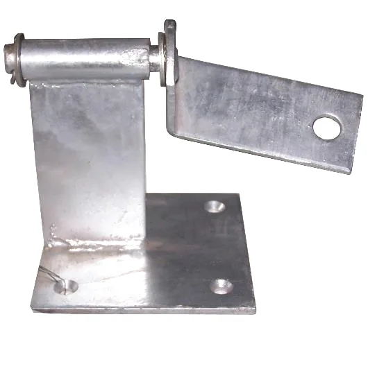
A tube that flares at one end and tapers at the other is carrying two different engineering instructions in a single piece of copper. The flare is a mechanical seal that has to be repeatable, because it will be undone and redone during service. The taper is a fusion joint, made once, permanently, and it is the only place where the part can fail without anybody noticing for years.
Both instructions fight each other. Forming a flare stretches the tube wall circumferentially; forming a taper deforms only the very end of the tube. Doing both means the first operation changes the condition of the material that the second operation depends on.
The taper is a joint geometry, not a chamfer
The tapered end exists to mate with a welding partner. A properly specified taper is not a lead-in chamfer; it is a defined cone whose angle, included angle and included length are all toleranced, because the weld quality is a direct function of how much surface the two parts present to each other.
Two angles dominate. A narrow taper presents a long, thin land and produces a deep, narrow weld pool — good for thin-wall joints, slow to fill, and demanding on arc control. A wider taper presents more area per unit length and fills faster, but it thins the joint face faster than the weld can build it back, which shows up as a lack of penetration at the root.
The geometry only functions if the mating part is held at a defined axial position. That means the taper alone is not enough — the tube needs either a stop shoulder or a defined projection from the mating part, otherwise the weld is made between two cones whose relative position is undefined, and the result is a weld with an unpredictable throat.
For this reason the productive specification for a tapered end includes:
- The taper angle, with its tolerance in degrees, not as “approximately”.
- The included length of the tapered land.
- The wall thickness at the root of the taper, which is the thinnest section of the joint.
- Any dimensional reference for axial position during welding — typically the projection from the shoulder.
H59 and H65 behave differently under forming
These grades are frequently treated as interchangeable on a purchase order. They are not, and the difference shows up most clearly in the flare.
Both are cartridge brasses — copper-tin-zinc — and both are formable. But the higher-tin grades in this family have higher yield strength and lower elongation. In practical terms, a grade with more strength and less ductility forms a sharper, cleaner taper and holds a crisper flare edge, at the cost of being less forgiving.
The consequence is a narrower process window. Where H59 can be flared with a moderate roll and come back cleanly, an equivalent operation on the higher-strength grade can:
- Crack at the inner surface first, because the inner surface sees the greatest strain in an expansion operation.
- Develop a longitudinal split that propagates well beyond the seal face, appearing later as a leak that is not where the joint is.
- Spring back after forming, so the flare angle measured at the assembly bench does not match the angle measured at the machine.
Grade selection is therefore a decision about the geometry, not about the material column. A part with an aggressive flare angle, or one that is expanded rather than roll-formed, wants the more ductile grade. A part with a shallow flare and tight dimensional demands can accept the stronger grade for better dimensional stability. Either way, the forming trial should be done on the actual grade, not on a sample of whatever was in the rack.
Work hardening decides whether the second operation is possible
The sequence matters and it should be explicit on the drawing.
If the taper is formed first, the tube end is already cold-worked, and the flare — which involves much greater strain because the whole circumference expands — happens on hardened material. That is the harder sequence. If the flare is formed first and the taper is machined or formed afterwards on the end of the already-hardened tube, the taper is a much lower-strain operation.
There is an additional argument for annealing between operations. A fully annealed tube forms cleanly in both operations and then work-hardens around the formed features, which is exactly the stress distribution you want in a pressure-containing part: highest in the formed regions where the geometry induced the strain, lower in the undeformed body.
Where both ends are formed and the part sees cyclic pressure, an anneal between the two forming steps is cheap and materially improves the consistency of both ends. Where the part is annealed and then left to age without further processing, plan for the dimensional movement that comes with stress relief and specify the final length after the last operation, not before it.
Flare angle and the seating face
The flare geometry is more constrained than most drawings admit. The usable angle depends on the wall thickness and the ductility of the material, and pushing past the limit produces a flare that seals initially and leaks after the first thermal cycle.
Three details decide whether a flare works:
- The seating face. The flat annular face that the nut face presses against. It must be square to the tube axis and flat, not conical. A slightly conical seating face is the most common cause of a flare that appears correct on the gauge and leaks under load, because the nut face contacts the high point only.
- The heel radius. The transition from the tube to the cone. A sharp heel is a stress raiser and a crack initiator; a proper radius spreads the strain.
- Wall thickness at the mouth. The flare thins the wall. If the drawing specifies the wall at the tube body and the flare is formed without a wall allowance, the finished flare sits below the minimum wall and becomes the initiation site for a split.
All three belong on the drawing with tolerances. A flare specified as “approx. 45 degrees” is a flare that will be formed differently on every machine in the shop and gauged differently on every bench.
Joint preparation decides more than the weld procedure
The tapered end has to be clean, and in copper that means chemically clean. The preparation sequence is:
- Degrease the taper and the adjacent tube body.
- Remove the oxide film by pickling, then rinse thoroughly — residual acid in the joint is a porosity source.
- Neutralise and dry. Water carried into a copper joint becomes porosity.
- Keep the joint protected between preparation and welding. Copper oxidises fast enough that a prepared taper left for an hour will need redoing.
The same care applies to the flare seat, in reverse: it wants to be clean and oxide-free, but it does not want to be etched or aggressively cleaned in a way that leaves a chemically altered surface under a sealing washer.
What inspection has to cover
For a dual-ended part like this, inspection has three layers and none of them can be skipped.
- Formed geometry. Taper angle and length by optical measurement, flare angle and height, and the squareness and flatness of the seating face. A height gauge cannot check the seating face flatness, so that one needs a fixture or a CMM.
- Wall integrity. Minimum wall at the taper root and at the flare mouth, measured on a sectioned sample or by ultrasonic wall measurement, because both are stress-raised sections where cracking starts.
- Joint performance. A hydrostatic or pneumatic test at design pressure for the finished weld, and a leak test on the flare seat assembly to prove the seating face works as designed rather than only that the tube formed.
Questions worth raising on the drawing
- Is the taper angle specified with a tolerance in degrees, and is the mating part’s geometry defined so the two can actually be aligned?
- Is the forming sequence written down — taper before flare or the reverse — and is an anneal called out between them?
- Is the grade chosen for the geometry, with the flare angle and expansion ratio considered, rather than ordered as a generic brass?
- Does the drawing give a minimum wall at the taper root and at the flare mouth, not just at the tube body?
- Is the seating face called out as flat and square, with the heel radius dimensioned?
- Does the inspection plan include a leak test of the assembled flare joint, or only a dimensional check of the formed tube?
That last question separates a part that has been formed from a part that has been proven. The dimensional check confirms the geometry; only the assembled leak test confirms the seating face, the nut material, and the actual torque applied in the field. Those three together are what determine whether the flare seals in service.
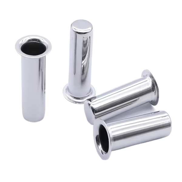
This part belongs to our Custom Metal Stamping Parts range. The custom metal stamping parts pages collect the process notes, common materials and inspection points behind every product in the family.
Specifications
| Item | Copper tube with flared mouth and tapered mouth welding H59 H65 |
|---|---|
| Brand | AUNOV |
| Designing | Made to your 2D/3D drawings (PDF, DWG, STEP, IGS) – a manufacturability review comes back with the quotation; the same drawing is used for every repeat order. |
| Tooling | Die design and toolmaking stay in house, so die cost stays transparent, and ownership is confirmed on the quotation. |
| Samples | Sample parts are measured and reported before submission, so any deviation is corrected at sample stage, and later batches are gauged back to the signed sample. |
| Materials | Copper T2 / T3, annealed for forming; conductivity and grain data recorded per production lot. |
| Surface finish | Plating, coating or polishing to suit the drawing; finish thickness and adhesion checked on the first article. |
| Processing | Laser or TIG welding of formed components, dressing and leak testing, then finishing. |
| Equipment | Press shop with 5-250 T mechanical presses and dedicated dies, with in-house toolmaking to keep dies and fixtures maintained. |
| Tolerance | +/-0.03 mm on pierced holes, +/-0.1 mm on formed sections; critical dimensions carry CMM data with the shipment. |
| Delivery terms | CIF or DDP, with FOB available, payment by T/T or L/C, quoted in USD or EUR; price breaks tie to annual volume. |
Related Products



Request a Quote for This Part
Send a drawing or sketch — get material advice, tooling cost and a per-piece price within 24 hours (working days).