
What a flange changes about the load path
A threaded joint carries its load along the thread helices. A flanged joint carries its load through a contact area, and that difference is not a matter of degree. Once a flange is involved, the joint’s capacity depends on how evenly the contact area is loaded, and the determining factor becomes bending rather than tension. This is why a flanged fitting can be made from the same material and the same wall thickness as a threaded one and still behave in a completely different way under load, and why copying a threaded design and adding a flange is one of the more reliable ways to produce a joint that passes a static calculation and fails in service.
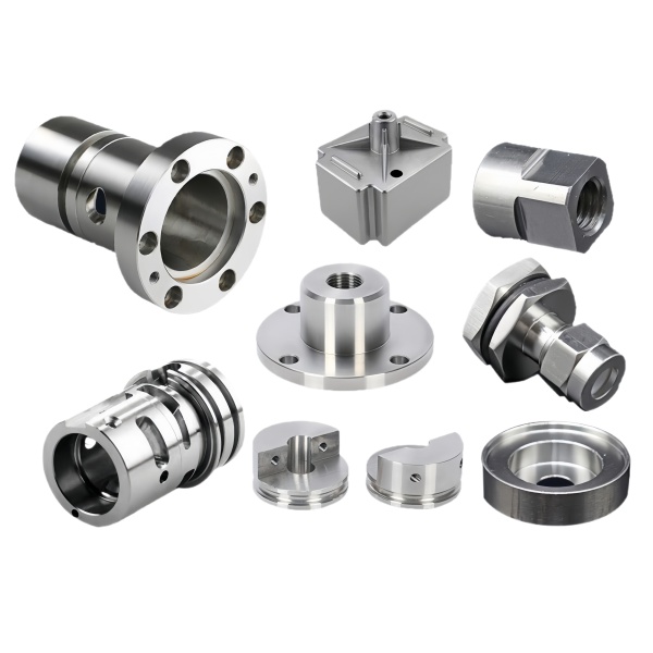
AUNOV machines stainless steel flanged fittings and their mating nuts on CNC turning centres to ±0.03 mm on machined features, from 304 and 316 grades, with finishing by passivation or plating per the drawing. The family covers flanged adapters, flange-mount fittings, and the hex or flanged nuts that complete the joint. This page deals with the mechanics that these parts share.
Tension versus bending, and where the moment comes from
A bolt tightened into a threaded port pulls along the axis of the thread. The load is nearly pure tension, the thread flanks share it over several engaged turns, and the fitting’s wall is loaded in tension and hoop stress. A flanged fitting still has the bolt tension, but it also has to transfer that tension into a flat contact face, and the transfer happens at a radius. The bolt force times the distance from the bolt line to the seal track is a bending moment, and the flange must resist it.
The consequences are specific and they explain most flange failures:
- The flange tries to rotate open about its inner edge. The contact pressure is highest near the bolts and falls toward the midpoint between them. If the seal track passes through a low-pressure bay, the seal opens there while the bolts remain fully tight. This is the classic “bolts are tight and it still leaks” report.
- Deflection scales with the cube of the unsupported span. Doubling the distance between two bolts increases the flange deflection between them by roughly a factor of eight, all else equal. Adding one bolt to a long bay is therefore far more effective than thickening the flange.
- Thin flanges take a permanent set. If the flange is loaded beyond its elastic range even once, the face is no longer flat and it will not seal again at the original preload. This is why a flange that leaks, is re-tightened hard, and then leaks again is often a flange that has been permanently deformed rather than one that was never tight enough.
- Stainless Steel has a low modulus relative to carbon steel. Roughly 10 percent lower for the common austenitic grades, which means slightly more deflection for the same geometry and load, and it means the preload sensitivity to bolt stretch is different.
Flange face geometry: flatness is a strength requirement
On a threaded joint, flatness of the seal face matters but the thread dominates. On a flanged joint, face flatness is a load path requirement. A face that is dished or conical by a few hundredths of a millimetre will contact only near its outer edge, where the bolts are, and the seal track will be unloaded. The joint then depends entirely on the gasket’s ability to bridge the gap, which is a fragile arrangement.
| Flange face attribute | Why it matters | Typical specification route |
|---|---|---|
| Flatness across the seal track | Determines whether the gasket is uniformly compressed | Measured over the seal track specifically, not over the whole face |
| Perpendicularity of the face to the thread axis | A skewed face loads the thread off-axis and bends the fitting | Controlled relative to the thread’s functional axis, measured on a gauge |
| Concentricity of the bore to the face | An eccentric bore narrows the seal track on one side | Tighter than the face’s own tolerance, because the seal track is the limiting path |
| Surface roughness on the seal track | A smooth track lets a soft gasket wet out; a rough track leaks around the asperities | Roughness specified with a prohibition on circumferential scratches |
| Radius or chamfer at the bore edge | A sharp inner edge cuts the gasket during assembly and during thermal movement | A controlled radius, called out because it is a functional feature not a deburring detail |
| Thread run-out length | Thread that runs into the flange face distorts the face when a fitting is tightened | An undercut or a thread relief specified so the mating part seats on a face |
The last row is worth pausing on. On a thin flanged fitting, the thread is often cut from the back and runs out partway through the flange. When a mating component is tightened against the flange face, its shoulder bears on the thread crests near the run-out rather than on the face, and the flange is pushed into a dish. A relief groove between the thread and the flange face costs one turning operation and removes the entire failure mode.
The nut is not an accessory; it is the preload element
In a flanged assembly the nut’s job is to generate and hold clamp load. Everything about it is a load-path feature, and treating it as a piece of hardware leads to specifications that say “hex nut, stainless steel” and nothing else.
- Nut height is the engaged thread length, and engaged thread length is where the load lives. For a stainless steel nut on a stainless steel stud, the load is shared across the engaged turns unevenly: the first few turns carry the majority. Too few engaged turns and those turns are overloaded; well beyond roughly one diameter of engagement the additional turns contribute little. Specifying nut height is therefore a load capacity decision, not a weight decision.
- Bearing face condition controls friction and therefore preload. For a given torque, the clamp load depends on the friction in the threads and under the nut face, and friction varies with finish and with lubrication. A passivated stainless steel face and a dry stainless steel face tightened to the same torque produce measurably different clamp loads. Where preload matters, torque has to be specified together with the friction condition, or the joint should be tightened by a method that measures something other than torque.
- Flanged nuts change the bearing area, not the load. A nut with an integral flange spreads the load over a larger area and reduces the surface pressure on whatever it bears against. On an aluminium or thin-walled mating part this matters, because the failure mode is local yielding rather than thread stripping. The flange also removes the need for a separate washer, provided it is a proper washer-faced nut rather than a nut with a decorative skirt.
- Nylon insert and all-metal locknuts behave differently at temperature. A nylon insert loses its locking effect at temperatures that an all-metal prevailing torque nut tolerates. For a stainless steel assembly in a hot environment, the all-metal type is the correct choice, and it should be named on the drawing.
- Galling between stainless steel nut and stainless steel stud is the most common assembly failure in this family. The thread flanks cold-weld under pressure and tear when the nut is removed, so the joint is ruined on its second assembly. The countermeasures are a lubricant, a dissimilar material pairing, or a coated thread, and the decision belongs at the design stage because it constrains the thread finish.
Passivation, plating and what each does to the thread
Finishing a flanged fitting is not cosmetic. The finish changes the pitch diameter and the friction coefficient, and both of those change the joint.
Passivation removes free iron and allows the passive layer to re-form. It is an acid treatment and it removes essentially no material, so thread dimensions are unaffected and a passivated thread will pass its gauge. Its effect on friction is modest, though a passivated surface used against a passivated surface is a galling-prone pairing unless lubricated.
Plating adds a layer. On a thread, the layer grows both crests and flanks, and the pitch diameter changes in proportion to the layer thickness: a plating of 8 micrometres per surface adds roughly 0.016 mm to the pitch diameter on one side, which is close to a whole tolerance grade on a small thread. For that reason a plated thread should either be cut with a pre-plate allowance on the pitch diameter, or masked, or checked after plating with the gauge that the customer will use. The same applies to the flange face, where plating rounds the bore edge chamfer and slightly changes the surface texture.
Where a plated finish is specified, it is worth saying which surface needs the plating and why. A fitting that is plated for appearance does not need the bore plated; a fitting plated for a wear or electrical reason may need specific surfaces plated and others masked. Given that the plating changes the dimensions, an unmotivated blanket specification is the most expensive kind.
Assembly, re-assembly and the second-tightening problem
A flanged joint that seals on the first assembly is not proven. The behaviour that matters is what happens after the joint has been disturbed, and there are three mechanisms that make the second assembly different from the first.
- Embedment. Surface asperities on the seal track and the gasket flatten on the first tightening, so the same torque produces a different clamp load and a different compression on the gasket. The second assembly usually needs a higher torque to reach the same gasket compression, and the customer should be told so.
- Thread relaxation in stainless steel. Stainless Steel threads under sustained load exhibit measurable creep at elevated temperature, so preload decays over time. Where the joint is hot and cycled, a re-torque interval is a legitimate requirement to put on the drawing.
- Gasket memory. A gasket with good recovery will follow the flange as it relaxes; one with poor recovery will not. Where a flange is thin and the thermal excursion is large, gasket recovery is the property that keeps the joint sealed, and it should be specified rather than inherited.
Specifying a flanged fitting and its nut
- Material grade and the environment, in particular whether chloride is present, which decides between 304 and 316.
- Pressure and temperature rating, and whether the pressure is cyclic.
- Flange face flatness over the seal track, with perpendicularity of the face to the thread axis.
- Seal-track surface roughness with a prohibition on circumferential defects.
- Bore edge radius, called out as a functional feature.
- Thread relief or undercut between the thread and the flange face.
- Nut type, height, bearing face, and whether a flange or a separate washer is used.
- Assembly torque with its friction or lubrication condition, and any re-torque requirement.
- Finish with the surfaces to be plated or masked stated explicitly.
- Whether the joint will be disturbed in service, which triggers the galling and embedment considerations.
More bolts allow a thinner flange, down to a limit set by the thread
Can the flange be thinner if more bolts are used?
To a point yes, because deflection between bolts falls sharply as the span shortens. But there is a practical minimum set by the thread’s engaged length and by the fitting’s own wall. The right sequence is to fix the bolt pattern first, then size the flange for the resulting span.
Why do stainless steel flanged joints seize on disassembly?
Galling, and it is a function of contact pressure, material similarity and the absence of a lubricant. When specifying a stainless steel-to-stainless steel threaded joint that will be taken apart, either require an assembly lubricant or choose a dissimilar pairing for one of the two components.
Does the finish change the torque I need?
Yes, substantially. Plated and passivated surfaces have different friction coefficients, and lubrication changes the relationship between torque and clamp load more than any dimensional change. If the joint’s preload is important, specify the finish and the lubricant together with the torque.
How many engaged threads does the nut need?
As a working figure, an engaged length of about one nut diameter is where the calculation typically lands for a stainless steel pair, and significantly less than that over-stresses the first turns while significantly more adds little capacity. The exact figure comes from the thread shear area against the proof load, which we are happy to run for a specific joint.
Parts like this one sit under the CNC Machining Parts range, whose overview page gathers the tooling logic, finishing options and tolerance notes shared across the family.
Specifications
| Item | Stainless Steel CNC Machined Flanged Fittings and Nuts |
|---|---|
| Brand | AUNOV |
| Designing | Send drawings, or send a nut sample to be measured, DFM feedback is returned with the quote. |
| Tooling | Tooling designed and cut in house, held under your part number. |
| Samples | Sample parts arrive with a full dimensional report and material certification. |
| Materials | 304 / 316 stainless steel leads the stock list for this part, alongside carbon steel (SPCC / DC01), aluminium, brass and copper, per the drawing. |
| Surface finish | Plating, e-coat, powder coating, anodising or passivation, fixed at the drawing review. |
| Processing | Staged deep drawing, with in-line annealing where the draw ratio requires, then pierced and CNC-machined in house. |
| Equipment | Mechanical presses 5-250 T and hydraulic presses 250-500 T, CNC turning centres and a climate-controlled CMM room. |
| Tolerance | Tolerances to +/-0.1 mm as drawn, machined features held to +/-0.03 mm. |
| Delivery terms | Standard terms FOB, DDP offered to EU and US, T/T or L/C, D/P on repeat business, call-off scheduling supported. |
Related Products



Request a Quote for This Part
Send a drawing or sketch — get material advice, tooling cost and a per-piece price within 24 hours (working days).