
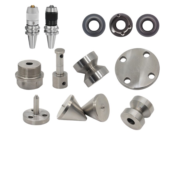
Spray nozzle orifice geometry determines the spray pattern more than the upstream pressure does
A machined spray nozzle—whether it is for coating, cooling, cleaning, humidification, or fuel atomization—produces its characteristic spray pattern through the interaction of fluid dynamics at the exit orifice. The shape and finish of that orifice have more influence on droplet size distribution, spray cone angle, and pattern uniformity than any change in supply pressure below the turbulent transition.
For a pressure-swirl nozzle (the most common type for industrial applications), the key geometric parameters are: swirl chamber inlet area (sets the tangential velocity), swirl chamber radius (sets the angular momentum), orifice diameter (sets the axial velocity), and the length-to-diameter ratio of the orifice approach passage. We machine these features using 5-axis simultaneous machining for complex swirl geometries or conventional milling + EDM for simple axial-flow nozzles. The critical tolerances are ±0.01 mm on orifice diameter and ±0.02 mm on swirl chamber dimensions—tight enough to keep spray cone angle within ±3° of nominal and flow rate within ±5 %.
Seal selection for a nozzle body depends on the fluid chemistry, temperature, and pressure rating
The seal (or seals) in a nozzle assembly prevent leakage between the nozzle body and its mounting interface, and between internal components if the nozzle has multiple sections. Seal selection follows a decision tree based on operating conditions:
- Fluid compatibility: Is the fluid compatible with elastomers? (Some solvents, fuels at high temperature, and aggressive chemicals require metal-to-metal or PTFE seals.) If yes → proceed to step 2. If no → use PTFE envelope seals or metal-to-metal contact.
- Temperature range: What are the minimum and maximum operating temperatures? Nitrile (NBR): -30 °C to +100 °C. Fluorocarbon (FKM/Viton): -20 °C to +200 °C. Silicone (VMQ): -60 °C to +200 °C (but poor oil resistance). PTFE: -200 °C to +260 °C (excellent temperature range but requires spring energizer for sealing force).
- Pressure rating: What is the system pressure? Standard O-rings handle up to ~20 MPa with proper groove design. Above 20 MPa → consider X-rings (quad rings) for better extrusion resistance, or metal C-rings for extreme pressure.
- Dynamic vs. static: Does the seal experience relative motion (rotating shaft, reciprocating piston)? Dynamic seals (lip seals, PTFE guide bands, wear rings) have different design criteria than static O-ring seals.
Flange component flatness and bolt pattern accuracy determine whether the gasket seals uniformly
A flange component—a mounting flange, an adapter flange, or a manway cover—relies on its flat face and bolt pattern to compress a gasket uniformly around the circumference. Non-uniform compression creates high-pressure zones (where the gasket may extrude into the bore) and low-pressure zones (where leakage occurs).
We machine flange faces to 0.01 mm TIR over the gasket area using a facing operation as the last machining step before cleaning. Bolt holes are positioned to true position ±0.15 mm diameter zone at MMC relative to the bore center (Datum A). For flanges above DN50 (approximately 60 mm bore) or pressures above 10 MPa, we tighten both tolerances: 0.005 mm TIR on the face and ±0.08 mm on bolt position.
Material selection for nozzle/seal/flange assemblies balances corrosion resistance, machinability, and cost
These components often see a combination of challenges: exposure to process fluids (corrosion), precision geometry requirements (machinability), and cost sensitivity (competitive pricing):
- Nozzle body: 316 stainless steel for water-based and chemical fluids; 303 stainless steel for fuel and oil where corrosion is less aggressive; 17-4 PH for high-pressure (> 30 MPa) applications where strength matters; brass for low-pressure (< 2 MPa) water or air nozzles where cost is the primary driver.
- Seal components: 316 stainless steel for metal seal rings and spring energizers; bronze (C95400) for wear rings running against steel shafts; PTFE-filled composites for guide bands and backup rings in chemical service.
- Flange: Usually matches the nozzle body material for galvanic compatibility. If the flange bolts to a dissimilar metal (e.g., aluminum housing), we recommend insulating gaskets or coated bolts to prevent galvanic corrosion at the flange interface.
How we functionally test a complete nozzle-seal-flange assembly before shipping
For orders where we supply the assembled unit (nozzle body + seals + flange + any internal components):
- Leak test at rated pressure: Assembly pressurized to 1.5× design pressure for 10 minutes using customer-specified fluid or surrogate. Acceptance: zero visible leakage from any interface (flange gasket, port threads, body porosity).
- Spray pattern verification: For nozzles with a specified pattern (cone angle, fan angle, full cone, hollow cone), we photograph the spray against a backlit grid and measure the pattern dimensions using image analysis software. Acceptance: within ±5 % of nominal for pattern angle and coverage area.
- Flow rate measurement: Calibrated flow meter measures actual flow at nominal pressure drop. Acceptance: within ±5 % of drawing specification. Parts outside this range are segregated for bore re-measurement (oversized/undersized orifice or swirl chamber).
- Cycle test (sample): One assembly per 200 parts undergoes 500 pressure cycles (0 → rated pressure → 0) at 1 Hz frequency. After cycling, the assembly is re-tested for leakage and flow rate. Acceptance: no degradation > 10 % from initial values. This catches fatigue-related issues (seal wear, flange relaxation, body creep) that would not appear in a single static test.
- Surface finish and coating verification: All external surfaces inspected for coating integrity (anodize thickness, plating adhesion, passivation completeness). Internal surfaces (bore, swirl chamber, orifice) checked for proper surface finish (Ra per drawing spec).
CNC Machining Parts is the parent range for parts like this one; the overview page gathers the tooling logic, finishing options and tolerance notes that apply across the family.
Specifications
| Item | CNC Machined Spray Nozzles Seals and Flange Components |
|---|---|
| Brand | AUNOV |
| Designing | Send us your 2D drawing, or mail a sample for measurement, our engineers reply with a manufacturability assessment and pricing. |
| Tooling | Dies designed and built in our own toolroom, with your part number on the tool record. |
| Samples | Approval samples of the component ship with a dimensional report and material certificate. |
| Materials | Carbon steel (SPCC / DC01), 304 / 316 stainless steel, aluminium, brass and copper are stocked, with the final grade confirmed at the drawing review. |
| Surface finish | Finish options: plating, e-coat, powder coating, anodising or passivation, fixed at the drawing review. |
| Processing | Staged deep drawing with in-line annealing where needed, then pierced and CNC-machined in house. |
| Equipment | Mechanical presses 5-250 T and hydraulic presses 250-500 T, CNC turning centres, climate-controlled CMM room. |
| Tolerance | +/-0.1 mm on as-drawn features, machined features held to +/-0.03 mm. |
| Delivery terms | Standard terms FOB, DDP offered to EU and US, payment T/T or L/C, D/P for repeat accounts, call-off schedules and blanket orders supported. |
Related Products


Request a Quote for This Part
Send a drawing or sketch — get material advice, tooling cost and a per-piece price within 24 hours (working days).