
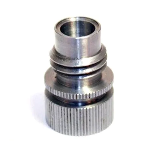
A knurled bushing is one of those parts where the drawing shows two features and the part has three. The diameter, the bore, and the knurl are all present, and the knurl is the one that quietly changes the other two. Because a knurl is cut, not pressed, and because it displaces material outward, a knurled bushing is not the diameter the print calls out. It is the diameter plus whatever the knurl adds.
That sounds trivial. It is not, because the bushing’s outer diameter is a fit – it goes into a housing bore and it may be the locating element for something inside it. If the knurl grows the outside by 0.3 mm, the fit has changed by 0.3 mm. And if the knurl is cut with a step, so that part of the OD is knurled and part is plain, then the part has two diameters that both have to be right and only one of them is on the print.
Why a bushing has a knurl at all
Knurling on a bushing does one or more of four things, and it helps to know which one before deciding how tight to make it.
- It prevents relative rotation. A plain bushing pressed into a bore can rotate under load. A knurled one resists that by mechanical interlock rather than by friction alone. This is the most common reason.
- It improves the press fit on the inside. A knurl on the OD bites into the housing bore as it is pressed, which raises the interference locally and improves stability, particularly on a hard or smooth housing material.
- It is a grip surface. If a hand tool, a thumb, or a lever engages the knurl, the knurl is a control feature and its geometry is what determines the force the user can apply. This is a completely different tolerance regime from a press-fit knurl.
- It is a tactile or index feature. Sometimes the knurl is simply what tells a user which way round a part goes. Then its visual consistency matters more than its dimensional accuracy.
These four uses have almost nothing in common dimensionally. A knurl that has to prevent rotation can be coarse and generous. A knurl that has to give a controlled grip has to be consistent in pitch and depth and often has to be specified in the axial direction too. A knurl on an index feature can be light. Deciding which job it is doing is the difference between a knurl that works and a knurl that is either too aggressive or slips.
How a knurl actually changes the part
Knurling is a cold-forming or cutting operation performed by a knurling wheel with a diamond-pattern or straight-pattern tooth form. Two effects matter downstream.
The first is radial growth. Material displaced by the knurl teeth moves outward and inward. On a thin-walled bushing the inward displacement is the significant one, because it reduces the bore. On a thick-walled bushing the growth is mostly outward. Which of these dominates is a function of the ratio of wall thickness to knurl depth, and on a stepped bore it is a function of where the step is. This is the specific reason a stepped bore and a knurl on the same part need to be planned together: the knurl that is over the thin section can close the bore there, and the knurl over the thick section does not close it but grows the OD, and the two sections then have different fits.
The second is residual stress and work hardening. Knurling is a forming operation. The surface layer is worked and the residual stress pattern around each tooth is a local stress concentration. On a bushing that is subsequently machined – and on most designs there is a bore operation after knurling, to get the bore to size and finish – the sequence matters. Knurling before boring gives a clean, stress-relieved-free bore but leaves the OD geometry slightly uncertain. Boring before knurling risks the knurl operation distorting an already-finished bore. The usual answer is to knurl first and bore second, and to state that sequence on the drawing so nobody reorders it.
Specifying a knurl
The bare minimum is the pattern type, the pitch, and the depth. Beyond that, several items make a knurlable part specify properly.
- Pattern: diamond versus straight. Diamond knurl pushes material in two directions and is self-cleaning and stronger. Straight knurl is a single direction, cuts more aggressively, and is what you use when the knurl needs to be cut on a hardened surface or when axial gripping is the goal. Naming the pattern matters because the two are not interchangeable and the depth-versus-pitch relationship differs.
- Pitch, stated as teeth per unit length or the equivalent, with a tolerance. A knurl that is 20 percent coarser than intended grips differently, and on a grip feature that difference is felt by the user.
- Depth, and where it is measured. Depth on a knurl is a radial dimension, and stating whether it is measured tooth-tip to the original diameter or tooth-tip to the root changes the number by twice the depth. This ambiguity causes real disputes and is worth closing explicitly.
- Which surfaces are knurled. On a stepped part, say whether the knurl runs over the step or stops at it. If it runs over it, the step is no longer a stop and the part can slide axially further than intended.
- The OD dimension, stated before or after knurling, or better, stated both ways: the plain OD and the knurled OD. This removes the single largest source of confusion on this part.
- Axial extent and whether it runs full length or is a band, because a banded knurl leaves a plain land that another component may use as an axial stop.
- Bore diameter and tolerance, held after the knurl operation, with the location where minimum material remains called out if the knurl overlaps the thin section.
- Whether the knurl is to be broken or deburred, and to what limit. Sharp knurl edges are a handling hazard and they will damage anything that slides over them.
The bore, which is the real precision feature
On a knurled bushing the bore carries whatever the bushing is meant to carry – a shaft, a pin, a plunger – and its size and finish are what actually determine the fit. Yet on a lot of these drawings the bore gets a general tolerance and the knurl gets a detailed callout, which is backwards.
A bore that receives a sliding shaft wants a clearance that accounts for thermal expansion of both parts, for the runout of whatever drives the shaft, and for the fact that the bushing is pressed into a housing and therefore already carries a press load. A bore that receives a rotating shaft wants to be specified for roundness rather than size, because a nominally in-size bore with poor roundness reads as a tight spot at one position and a loose fit at another. And a bore that is a location for a press-fit member wants a size and a roundness and, if the member is a thin-wall part, a much smaller band than the general tolerance.
The useful move is to state the bore as a functional fit rather than as a number. A limit fit to a stated shaft, or a clearance range with a note on what is being cleared, tells a machinist what the bore is for and lets them choose the process. A number without that context makes every one of them guess.
Material and temper, because a knurl changes the machining
Aluminium in the 5000 series machines well and knurls well. 6061 is the general answer but it is a compromise: it machines, it knurls, and it holds reasonable strength, and it is what most buyers ask for without thinking. Where a bushing sees significant load, a 5000 series or a higher-strength extruded grade will usually give a better combination of knurl depth and wall strength than 6061, because the knurl needs material to displace and 6061 does not displace it gracefully at depth.
Stock thickness here is in the 0.5 to 3.0 mm range, which means these are thin-walled parts and the knurl depth is a significant fraction of the wall. On a 0.8 mm wall, a 0.25 mm knurl is not a surface texture – it is a third of the wall. That case needs the knurl and the bore planned together, and it often needs the knurl reduced or moved to a thicker local section.
Turn the OD and the step, bore, then cut the knurl
CNC turning with milling and drilling in as few setups as the geometry allows is the right shape of route here, and the knurling operation slots into it. The efficient sequence is generally: turn the OD and the step, bore, then knurl – or turn, knurl, then bore, depending on whether the bore is meant to be finished after knurl distortion or not. Whichever it is, it belongs on the routing sheet, because a knurl operation moved from one end of the route to the other will change both the OD and the bore.
Tolerance of +/-0.005 mm is achievable on ground faces where the drawing demands it, and on this part the ground face that matters is usually the bore and the mounting shoulder. The knurl itself does not need that, and holding it there is a waste of money and of cycle time.
A knurl gauge reading means little until you measure both diameters
- Knurl depth and pitch on a first article, measured with a knurl gauge or by optical comparison against a master, on the same basis every time.
- Knurled OD and plain OD both measured, because a part can pass one check and fail the other, and only the pair tells you whether the knurl is right.
- Bore size, roundness and finish, with the bore measured after knurling, not before.
- Shoulder position and OD concentricity to the bore, which is what makes the bushing locate rather than merely fit.
- A functional check in the housing, if the knurl’s purpose is anti-rotation or grip. This is the test that actually confirms the feature works, and it takes seconds.
Knurled at all, or a plain bushing with a press fit
Does the bushing need to be knurled at all, or would a plain bushing with a press fit, a retaining feature, or a bonded joint do the same job more cheaply and more repeatably? Knurling is a good feature when the part is a light press-in component that must not rotate, and it is a poor substitute for a proper retention design when the loads are significant. On a thin-walled aluminium bushing, the knurl is also the feature most likely to eat the wall you needed for stiffness. It is worth confirming that the knurl is solving the actual problem before it is specified, because removing it simplifies the part, removes a tolerance, removes a tooling operation and usually lowers the cost.
Our CNC Machining Parts range is where this part sits. The cnc machining parts pages carry the process notes, common materials and inspection points behind every product in the family.
Specifications
| Item | Knurled Aluminum Bushing with Stepped Bore |
|---|---|
| Brand | AUNOV |
| Designing | Your drawing sets the part – samples are reverse-measured into a controlled drawing; changes are priced before they are made. |
| Tooling | Die design and toolmaking stay in house, so the die charge appears as its own quotation line, and first-article timing is measured from the tooling start date. |
| Samples | First-article samples ship with a dimensional report and material certificate, so the part is proven before it is made in volume, and the signed sample is kept for future reorders. |
| Materials | 1050 / 3003 / 5052 / 6061 aluminium, 0.5-3.0 mm stock – temper matched to the forming depth or machining route of this ring. |
| Surface finish | Finish selected from the drawing: plating, coating, anodising or passivation; finish thickness and adhesion checked on the first article. |
| Processing | CNC turning with milling and drilling in as few setups as the geometry allows; first articles verify the whole flow before the run is released. |
| Equipment | CNC turning centres with bar feeders and 3-/4-axis machining centres; first articles and batch samples are checked on the CMM. |
| Tolerance | +/-0.005 mm achievable on ground faces where the print demands it; critical dimensions carry CMM data with the shipment. |
| Delivery terms | FOB Ningbo or Shanghai, payment by T/T or L/C, quoted in USD or EUR; repeat orders reuse the approved first article. |
Related Products


Request a Quote for This Part
Send a drawing or sketch — get material advice, tooling cost and a per-piece price within 24 hours (working days).