
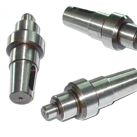
A threaded aluminium sleeve is a plain part with a plain job, and the entire reason it needs to be machined rather than cut from tube or made from a fastener is that it has to do two things at once that conflict: it has to thread cleanly, and it has to do something with heat.
Which of those two is the design driver is worth establishing before anything else, because it changes the alloy, the wall thickness, and whether the sleeve’s bore has a tolerance at all.
A sleeve does one of three jobs, and they are not interchangeable
It is a standoff
The simplest case: a threaded sleeve that spaces two components apart and takes the load between them. Here the requirements are straightforward – the thread must carry the compressive load, the sleeve must not buckle if it is slender, and the length is a spacing dimension.
- Thread engagement is the strength limit. A sleeve’s height is a strength dimension because it determines how many engaged turns it has, and on a slender sleeve that is the difference between a joint that holds and one that strips.
- Buckling is the other limit. A slender sleeve under compression will buckle, and its slenderness – length divided by radius of gyration – is what decides. The fix is a thicker wall or a shorter length, and it is worth knowing which of the two the design has room for.
It is a heat path
The sleeve exists to carry heat from one surface to another – from a power device to a heatsink, from a sensor to a measurement. This is the case that changes everything about the material and the dimensions.
- Aluminium is the right material for the bulk and it is chosen because of this. A sleeve that carries heat is being asked to be a conductor, and aluminium’s volumetric thermal conductivity is several times that of the steel it would otherwise be made from.
- But the interfaces dominate. This is the point that is missed on nearly every heat-carrying sleeve. The path runs from the device, across an interface, into the sleeve’s wall, across another interface, into the heatsink. The metal in the middle is rarely the bottleneck. On a sleeve bolted between two surfaces, the bolted interfaces are usually a far larger thermal resistance than the aluminium wall, and the sleeve is buying very little for the space it takes.
- So the questions on a heat-carrying sleeve are: what thermal interface material is specified, is it specified to a thickness and a conductivity, is the sleeve’s faces flat enough for that material to make contact over its area rather than bridging the high points, and is the sleeve even in compression at those faces or is it rattling loose. A thermal sleeve that is not clamped tightly is worse than no sleeve, because it looks like a solution.
- Anodising makes it worse. The oxide layer is a thermal insulator, and if a heat-carrying sleeve is anodised without masking its faces, the sleeve becomes a good insulator and a poor conductor. This is a real and common mistake and the fix is a masking list.
It is an insulator or a mount
A threaded sleeve on a plastic or an electronic assembly is often there purely to hold a threaded insert, a standoff, or a screw, and to keep metal-to-metal contact away from something that must not be metal-to-metal. Here the requirements are about galvanic isolation and about not crushing the thing being held, and the thread’s length matters because a long thread into a plastic boss will crack it.
Threaded aluminium, which is a genuinely awkward feature
Aluminium’s threads are the part of this item that needs the most care, and there are two distinct problems.
A cut thread in aluminium has low stripping strength
An aluminium thread’s failure mode is almost always stripping in the first few engaged turns rather than breaking at the root. This means the thread’s strength is governed by the material’s shear strength over the engaged area, which is much lower than the metal’s tensile strength would suggest.
- More engagement helps. Each additional engaged turn adds shear area, and unlike a steel thread the aluminium thread will reach its limit gradually rather than suddenly – so more engagement is a real gain.
- Longer engagement has a practical limit. It needs a longer sleeve, and a longer sleeve in a bolted joint is more likely to be unparallel, which loads only part of the thread and reduces the effective engagement.
- Thread-forming or thread-cutting screws should be specified, and they are what makes an aluminium thread acceptable. A screw that forms its own thread in the aluminium engages the full thread profile rather than stripping it. Where a self-tapping or thread-forming screw is used, its specification is part of the sleeve’s specification.
- Where the joint will be assembled and disassembled repeatedly, a steel insert is the correct answer and it is worth saying so. Pressed or threaded brass or stainless steel inserts turn an aluminium threaded part into an ordinary threaded part and they do it without changing the part’s geometry much.
The thread’s depth and the wall
An aluminium thread has a real depth, and a thin-walled sleeve does not have much material to give. The requirements interact:
- The wall must be thick enough for the thread, or the thread will break through the wall. On a sleeve with a thin wall this is the limiting dimension and it should be checked rather than assumed.
- The thread’s root diameter is the sleeve’s weakest section, because the thread’s root is a notch and the material there is in tension under the screw’s axial load.
- Where the sleeve is hollow and the thread is on the outside, the bore’s diameter and the thread’s root diameter define the wall and they must be coordinated – and the thread is normally the smaller of the two.
- Tapping into a thin wall produces burrs on the inside face, and an internal burr on a part that may go into a fluid or a heat path is a functional defect.
Material, and the specific alloys
Carbon steel, 304 and 316 stainless steel, aluminium and brass are held, with substitutions proposed only in writing. On a threaded sleeve the aluminium grades do specific jobs.
- 6061 for general duty and for a heat-carrying sleeve where the machining matters. It is the free-machining aluminium and it takes a threading operation well.
- 6063 where appearance or a decorative anodise is involved – lower silicon and iron, so it anodises more consistently.
- 5052 where the sleeve needs to carry a load in a corrosive environment; it has better corrosion resistance and good fatigue behaviour, at some cost in machinability.
- Hard anodising where the thread is a wear item and the alloy is chosen for it – 6061 or 6063 for decorative, and a hard-anodisable alloy where wear is the requirement.
And the substitution question worth raising: if the sleeve’s only job is to space two components and carry no heat, then a steel or brass sleeve is stronger, harder-wearing, and possibly cheaper than an aluminium one. The reason aluminium is specified on a plain standoff is usually thermal or weight, and if neither applies it is worth asking why.
Surface treatment, and the masking that decides whether it works
Surface treatment matched to the duty – plating, coating or polishing – with the agreed finish travelling with the part number. On a threaded sleeve the finish has four specific consequences.
- The thread. Any coating on a thread changes the fit, and a coated thread in an aluminium sleeve is doubly bad because the coating changes the fit and the coating is harder than the aluminium. Threads should be masked, or the coating specified as post-thread with an allowance for its thickness on the pitch diameter.
- Any face that makes thermal contact – masked, or the whole thermal argument for the part is lost.
- Any bearing or seating face – the anodised surface is harder and rougher and it will change both the friction and the wear behaviour of whatever seats on it.
- The appearance, where a decorative anodise is the requirement. On a small sleeve with a machined thread, the anodised surface’s appearance and the machined thread’s appearance will differ noticeably, and an approved sample settles it.
Tolerance, and where it belongs
+/-0.01 mm on critical bores, confirmed at the DFM stage, GD&T per drawing, PPAP-style reports on request. On this part the flagged dimensions depend entirely on which of the three jobs it is doing, and that is worth spelling out because it is the fastest way to write a correct tolerance scheme.
- Thread: pitch diameter, class, and the gauge to be used. A thread specification without a class is not a specification, and on an aluminium sleeve the class matters more than on a steel one because the material’s strength is the limit.
- The length, stated post-finish where the finish is on an end face, and this is a coordination dimension with the assembly.
- The bore, as a fit to whatever enters it, or at general tolerance where it is simply a clearance.
- Face flatness and perpendicularity, where the sleeve seats against something – on a heat-carrying sleeve this is functionally important because it determines whether the thermal interface material makes contact.
- Concentricity of the thread to the bore where both exist and the relationship matters.
- Wall thickness at the thread’s root as a minimum, because it is the structural limit and it is invisible.
First article release is a gate on the whole flow, not paperwork
First articles verifying the whole flow before the run is released, dimensional reports accompanying the first article, in-process checks between stages. The reliable items on this part:
- Thread gauging on every part – a go/no-go minimum and maximum, and the pitch diameter where the class requires it.
- Bore diameter and roundness, as a fit if it is a fit.
- Length, post-finish, where the finish is on an end.
- Face flatness and perpendicularity, and on a heat-carrying sleeve a check that the mating face is free of machining witness that would stand the sleeve off from its thermal interface.
- Wall thickness at the thread root, on a first article, as a specific check rather than an inference.
- Finishing thickness and adhesion on the first article, with the masked thread and any masked thermal faces verified.
- PPAP-style reports on request, which on a threaded part that will be assembled many times is worth having for the ordinary reason – it makes the fit traceable when a joint strips in the field.
Carrying heat, or just holding two things apart
Is this sleeve carrying heat, or just holding two things apart? The answer decides the whole part. If it is carrying heat, then the sleeve’s material is justified, its faces must be masked from anodising, its faces must be flat enough to seal against a thermal interface, and the real thermal design question is the interface and the clamping rather than the aluminium. If it is just spacing two things apart, then the sleeve is a fastener-shaped part and the material might be steel or brass, the anodising is purely cosmetic, and the only thing that really matters is the thread’s strength and the length’s coordination with the assembly. This is worth establishing before the enquiry is priced, because a heat-carrying sleeve and a cosmetic standoff sleeve look identical in a drawing and differ in almost every dimension of how they are specified.
This part belongs to our CNC Machining Parts range. The cnc machining parts pages collect the process notes, common materials and inspection points behind every product in the family.
Specifications
| Item | Aluminum Threaded CNC Machined Sleeve |
|---|---|
| Brand | AUNOV |
| Designing | Quotation follows the print, not a catalogue – samples are reverse-measured into a controlled drawing; revisions are re-quoted once rather than silently absorbed. |
| Tooling | Tooling is built and held under your part number, so a die can be re-cut against the approved drawing, and first-article timing is measured from the tooling start date. |
| Samples | Samples are issued for approval before the run, so the part is proven before it is made in volume, and production starts only after your written sign-off. |
| Materials | Carbon steel, 304 / 316 stainless steel, aluminium and brass are all held in stock; material substitutes are proposed only with your written approval. |
| Surface finish | Surface treatment matched to the duty: plating, coating or polishing; the agreed finish travels with the part number. |
| Processing | Bar-fed turning with milled features completed in the same clamping; first articles verify the whole flow before the run is released. |
| Equipment | Bar-fed CNC turning centres plus 3- and 4-axis machining centres, with in-house toolmaking to keep dies and fixtures maintained. |
| Tolerance | +/-0.01 mm on critical bores, confirms at DFM stage; GD&T per drawing, PPAP-style reports on request. |
| Delivery terms | FOB with DDP offered for EU and US addresses; payment T/T or L/C, freight quoted to destination. |
Related Products


Request a Quote for This Part
Send a drawing or sketch — get material advice, tooling cost and a per-piece price within 24 hours (working days).