
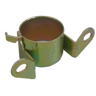
Datums first: how a wiper motor frame earns its accuracy
A wiper motor frame succeeds or fails on its datum scheme. The frame is the part every other component measures against – bearings locate from it, the gear housing pilots to it, the vehicle mounts through it – and if the drawing’s datums do not match the functional hierarchy of those interfaces, the frame will be “in spec” and still assemble badly. Before any discussion of draw ratios or tolerances, this is the conversation we insist on having: which faces actually locate what, in what order.
Building the datum hierarchy
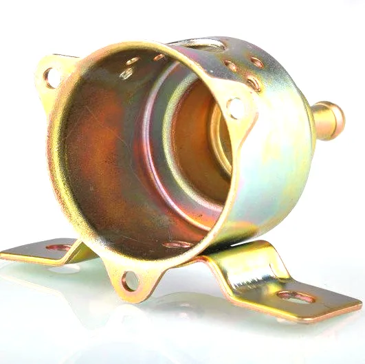
For a drawn wiper frame the functional hierarchy almost always resolves to three levels. Primary: the flange face that bolts to the motor’s main structure – it sets axial position for everything stacked against it. Secondary: the pilot diameter that centres the gear housing – it sets the concentricity that keeps gear backlash and shaft seal life honest. Tertiary: the bearing bores and mounting ear pattern, which position the rotating assembly and the vehicle interface respectively. When the drawing calls these out in the right order, every downstream measurement – ours and the customer’s – agrees by construction. When the datums are inherited from a machining drawing (an edge, or a random flange hole, as primary), inspection reports diverge from assembly reality and both sides waste weeks reconciling.
What the draw process holds and what it needs help with
Drawing gives the frame its shape in one stroke, and the process carries its own accuracy signature: flange faces come out flat to a few tenths after restrike, diameters hold 0.1-0.2 mm, and positions of in-die features land within 0.1 mm of their draw datums. Bearing-grade features exceed that – a spindle bore at H7 with 0.03 mm position is a machining or coining job regardless of how well the shell draws. The design pattern we recommend most: let the frame carry every locating function (faces, pilots, datums), and confine machining to the bearing seats alone. That division keeps machining fixtures simple – the part locates on its own drawn datums, no exotic fixturing – and keeps the tolerance budget where it matters.
GD&T that a stamping can actually honour
Frames often arrive with tolerances transplanted from cast or machined predecessors. Three adjustments make them stamping-native. Composite position for the ear pattern: the pattern’s mutual spacing tight, its position to the datums looser – because the vehicle cares about the pattern fitting, the motor cares about where the pattern sits. Profile on the flange face rather than flatness-plus-location separately: one callout the die can be tuned against. AndMMC (maximum material condition) modifiers on clearance features, which convert impossible fixed tolerances into honest functional gauges. Each of these is a five-minute drawing edit, and each removes either cost or sorting from the programme permanently.
Gauging strategy: checking the frame the way the assembly will use it
A frame’s gauges should mirror its datums. Our standard set: a functional gauge for the ear pattern (checks the vehicle fit), a pilot-diameter ring and flange-face sweep (checks the gear housing seat), and air or plug gauges for any machined bores. SPC runs on the secondary pilot and the bearing seats – the two features whose drift would reach the motor – while the pattern gauge runs as attribute checks. This gauging plan goes into the die kickoff so the gauges are built in parallel with the tooling, and first articles arrive with their measurement method already agreed rather than negotiated after a dispute.
We quote it, then propose datums in writing
The frame drawing – ideally with datums already harmonized to the function hierarchy above, or with a note inviting our review. Add the interfaces (what pilots to it, what bolts through it, what rotates in it), annual volume, and any machining scope you expect us to carry. First articles in three to four weeks after die approval, with the functional gauges delivered alongside.
Our frame drawing has no datums at all
Our frame drawing has no datums at all – can you still quote?
Yes, and we will propose a scheme in the quote review. It costs a day and prevents the classic outcome where the frame passes our CMM and fails their assembly gauge because each measured from a different origin.
Can you match the datums of our existing frame exactly?
Yes – for replacement programmes we copy the incumbent’s datum scheme even when we would draw it differently, because your gauges and fixtures already embody it. New-programme frames get the review; service frames get the match.
Who owns the machining fixtures if you machine the bearing seats?
The fixtures are ours and stay here; the datum scheme, gauges and process sheets are yours. If the programme moves, the frame drawing plus gauge set travels, and any competent shop can reproduce the machining cell from the documentation.
Automotive Motor Components is the parent range for parts like this one; the overview page gathers the tooling logic, finishing options and tolerance notes that apply across the family.
Specifications
| Item | Wiper motor frame |
|---|---|
| Brand | AUNOV |
| Designing | Made to your 2D/3D drawings (PDF, DWG, STEP, IGS) – a manufacturability review comes back with the quotation; the same drawing is used for every repeat order. |
| Tooling | Progressive and drawing dies are designed and built in house, so the die charge appears as its own quotation line, and first-article timing is measured from the tooling start date. |
| Samples | Samples are issued for approval before the run, so the sample is retained as the master, and later batches are gauged back to the signed sample. |
| Materials | Stock list: carbon steel, 304 / 316 stainless steel, aluminium, brass; the final grade is fixed at the drawing review. |
| Surface finish | Adhesion comes from phosphating, followed by powder coating, e-coating or zinc plating; visible faces get chrome or nickel. |
| Processing | Coil blanking, progressive drawing through 3-5 stages with anneals between, trim and pierce, then deburr and finish. |
| Equipment | Mechanical presses 5-250 T, hydraulic presses 250-500 T, an in-line annealing furnace, and CNC turning for secondary work. |
| Tolerance | +/-0.1 mm to +/-0.2 mm general; critical features held to the drawing and verified on the first article. |
| Delivery terms | CIF or DDP, with FOB available, payment by T/T, L/C at sight or D/P; repeat orders reuse the approved first article. |
Related Products
Request a Quote for This Part
Send a drawing or sketch — get material advice, tooling cost and a per-piece price within 24 hours (working days).