
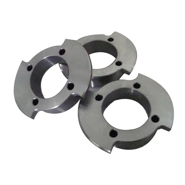
Custom CNC machining: the drawing is the process, and the process is the price
On a custom CNC machining part, the customer is not buying a feature list – they are buying a sequence of operations, and the sequence is visible on their drawing whether they intended it to be or not. Every feature that must be reached from a different direction, every feature that requires a different kind of tool, every tolerance that demands a finishing operation, appears in the price. The useful conversation is therefore not “what does this part cost” but “how many times does the part have to be set up, and can the drawing be arranged to reduce that”.
We run CNC turning with milling and drilling in as few setups as the geometry allows, on bar-fed CNC turning centres plus 3- and 4-axis machining centres with CNC turning centres for secondary operations and CMM inspection. First articles verify the whole flow before the run is released, ground diameters run to +/-0.01 mm with GD&T taken from your print, and capability is checked on the first article before the run continues. Stock covers carbon steel in SPCC and DC01 grades, 304 and 316 stainless steel, aluminium and brass, with material substitutes proposed only with your written approval. Samples are issued for approval before the run and mass production is gated on that approval. This page covers the seven decisions that determine whether a custom part lands well.
Decision 1: how many setups, and can the drawing change that number
Setup count is the largest single lever on a custom part’s cost and its accuracy. Every setup means a new datum, a new error contribution, a handling step, and a fixture. The design moves that reduce it:
- Cluster features. If two holes can be drilled from the same side, put them on the same side. If they must be opposite, that is two setups unless a machine can reach both – which a 3- or 4-axis machine often can, and this is a real question worth asking rather than assuming.
- Turn it or mill it, but do not do both unless you must. A part that is mostly round with a couple of milled features is a turn-mill part. A prismatic part milled from one side is a milling part. A part that genuinely needs both in separate machines has two operations and should be priced as such.
- Add a clamping flat. A part designed without a clamping surface gets clamped on something functional, or gets fixtured in a way that costs more than the flat was worth.
- Make the datum a real feature. Locating everything from one machined face means the process has one datum, not three.
- Make features symmetrical about a plane the machine can work from. Symmetry often means a single program and a single setup where an asymmetric version needs mirroring and a second pass.
Decision 2: which dimension is genuinely tight
Ground diameters to +/-0.01 mm is achievable, and the mechanism is the same on any material: a grinding or finishing operation, its own setup, and a handling route that protects the finished surface. Three points where custom parts go wrong:
- Asking for the tight band everywhere. On a part with twelve dimensions, making all twelve +/-0.01 mm is expensive and unnecessary. Naming the three that matter and flagging them produces a better part at a better price.
- Tight size but loose location. A diameter at +/-0.01 mm machined in a second setup can easily be 0.1 mm from where the print intended it. If position matters, it has to be machined in the setup that controls the reference, or the print has to accept the stack.
- GD&T that does not match the feature. This is the single most common cause of a custom part that arrives technically compliant and unusable. A position callout on a feature does not control its size. A profile callout controls form and orientation but not size. A flatness callout on a face does not locate it. If you are unsure which control to use, stating the functional requirement in words alongside the drawing is better than guessing at a symbol.
Decision 3: the material, confirmed rather than assumed
Material substitutes are proposed only with your written approval, and on a custom part that is the right rule. A substitution looks harmless and is not, because it changes properties that the design depends on:
- Carbon steel to free-machining steel. Much cheaper to cut, but not suitable for some welding and not suitable where a surface must be plated identically to a reference part.
- 304 substituted for 316. The single most consequential substitution on a stainless steel part, and in a chloride environment it is the difference between a five-year part and a one-year part.
- Aluminium substituted for steel on a structural part. Different modulus, different thermal expansion, different corrosion behaviour, different weldability, and a completely different fatigue picture.
- Temper changes within an alloy. Often invisible on a drawing and decisive for a spring, a clip, or anything that depends on a hardness value.
Where a part has a certification, a pressure, or a safety role, the material is a specification rather than a preference and the certificate should be part of the order.
Decision 4: the finish, and the operation it adds
Natural, plated or coated – the print decides, the agreed finish is logged, and the agreed finish travels with the part number. That last part is worth emphasising, because a finish change without a part number change is how a repeat order ends up subtly different from the original batch.
Three questions the finish answers:
- Masked features. Threads, bores, sealing faces, and any datum that must stay at a stated size. Masking is a planned operation with a real cost.
- Size before or after. On a +/-0.01 mm dimension this is not a rounding matter. State it.
- Sequence. Masking has to happen at a specific point in the route, which fixes the order of operations. A tapped hole machined after plating has a different fit than one plated after tapping, and which is right depends on the assembly.
Laser marking is available where needed and is worth specifying for a custom part where traceability matters – particularly where two parts with the same geometry run in different materials or for different customers, and a mixing error would be silent.
Decision 5: the edge condition
On a machined part the edges are the most common source of a functional complaint that no dimension report would have caught. Every sharp machined edge is a potential cut hazard, a potential burr, and a stress raiser. Four options:
- Specify a chamfer. The cheapest and most controllable: a small chamfer at a stated size and angle on every functional edge. It also improves handling and reduces nicking during assembly.
- Specify a radius. Where the edge must not cut, a stated minimum radius is the correct call.
- Deburr. Appropriate where edges are not functional, but it is a vague term and a specified burr limit is better.
- Specify nothing. Acceptable on a part where every edge is internal and hidden. Not acceptable on a part a person touches, assembles, or that goes through a person’s hands in service.
Decision 6: prototype first, or production first
Samples are issued for approval before the run, so the part is proven before it is made in volume, and mass production is gated on that approval. On a custom part this is often the best money a customer can spend, because a prototype catches the four things a drawing review cannot:
- A tolerance stack that does not close. Sometimes the individual tolerances are all achievable and the stack across a chain of features is not.
- An interference that the 3D model did not show. Models do not model fasteners, seals, adhesive, paint, and thermal growth.
- An assembly sequence that needs a tool that does not fit in the space. Extremely common and invisible on a drawing.
- A finish that looks different on the real part. Especially where the part is visual or where the finish is doing a functional job.
The alternative – producing a batch against an unproven drawing – is defensible only for a low-cost, low-risk part where the feedback would arrive cheaply anyway. On a tight-tolerance custom part it is the expensive route.
Decision 7: inspection depth
GD&T is taken from your print, capability is checked on the first article before the run continues, and CMM inspection is available. The question worth asking is which dimensions go on the report, because a report that measures everything is not more useful than one that measures the right things. Three useful practices:
- Report the controlling dimensions, not the whole drawing. The controlling dimensions are the ones that would cause a functional failure.
- Keep the approved first article as a physical gauge reference. On a custom part that is the only thing that defines the intent when a drawing note is ambiguous.
- Specify what happens on a borderline part. A defined acceptance rule written before the first batch is much better than an argument after it.
What to send, and what you get back
Quotation follows the print, not a catalogue, with unusual walls, threads or tolerances feasibility-checked first and the same drawing used for every repeat order. Dies, fixtures and gauges are made in our own toolroom so tooling lead time stays under our control, and ownership is confirmed on the quotation – which matters because on a custom part a dedicated fixture is a significant asset and its ownership should never be ambiguous.
Seven items make an accurate quotation, in descending order of value:
- The drawing as a native file (STEP or IGS), not only a PDF. A native model lets manufacturability be checked properly rather than approximated from a drawing.
- A note of which dimensions are functional and which are not. This is the single highest-value sentence on an enquiry.
- The assembly it goes into, or at least the mating part and its tolerances.
- Batch size, and whether it repeats. A one-off and a production run should not be quoted the same way.
- Material grade, and whether it is a preference or a requirement.
- Finish, including masked features and whether dimensions are before or after.
- Any certification, pressure, or safety requirement.
If a prototype stage makes sense, say so and we will quote it separately – which is also the cleanest way to find out whether the drawing closes before committing to a production price.
Our CNC Machining Parts range is where this part sits. The cnc machining parts pages carry the process notes, common materials and inspection points behind every product in the family.
Where this part is used
A custom CNC machined part is bought as a sequence of operations, and that sequence is visible on the drawing whether the customer intended it to be or not. Every feature that has to be reached from a different direction, every feature needing a different kind of tool, and every tolerance demanding a finishing operation appears in the price. The useful conversation is therefore not what this part costs but how many times it has to be set up and whether the drawing can be arranged to reduce that number.
These parts come from buyers who have moved a product from prototype into production, or who need a second source for a part their original supplier no longer wants to run. In both cases the drawing usually exists and the tolerance usually has a reason behind it. The value we add is in reading that drawing as a process – deciding which dimensions are genuinely tight, which material route is right, and where inspection depth is worth spending money on.
What we need to quote it
Send the drawing with the critical dimensions flagged and the material confirmed rather than assumed, and tell us the annual quantity and whether you want prototype or production first. If a first article is needed before the run, say who approves it and when – that gate is often where the schedule really sits. First articles verify the whole flow before the run is released, and samples are issued for approval, with mass production gated on that approval in writing.
Specifications
| Item | Custom CNC Machining Parts |
|---|---|
| Brand | AUNOV |
| Designing | Quotation follows the print, not a catalogue – unusual walls, threads or tolerances are feasibility-checked first; the same drawing is used for every repeat order. |
| Tooling | Dies, fixtures and gauges are made in our own toolroom, so tooling lead time stays under our control, and ownership is confirmed on the quotation. |
| Samples | Samples are issued for approval before the run, so the part is proven before it is made in volume, and mass production is gated on that approval. |
| Materials | Stock covers carbon steel (SPCC / DC01), 304 / 316 stainless steel, aluminium and brass; material substitutes are proposed only with your written approval. |
| Surface finish | Natural, plated or coated – the print decides, and the agreed finish is logged; the agreed finish travels with the part number. |
| Processing | CNC turning with milling and drilling in as few setups as the geometry allows; first articles verify the whole flow before the run is released. |
| Equipment | Bar-fed CNC turning centres plus 3- and 4-axis machining centres, with CNC turning centres for secondary operations and CMM inspection. |
| Tolerance | +/-0.01 mm on ground diameters, with GD&T taken from your print; capability is checked on the first article before the run continues. |
| Delivery terms | Delivery quoted per Incoterms 2020 – FOB, CIF or DDP – by sea or air, to your address. |
Related Products


Request a Quote for This Part
Send a drawing or sketch — get material advice, tooling cost and a per-piece price within 24 hours (working days).