
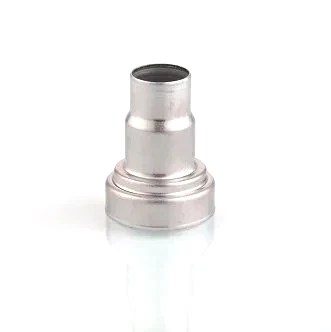
A sensor housing has two interiors and only one of them is allowed to change
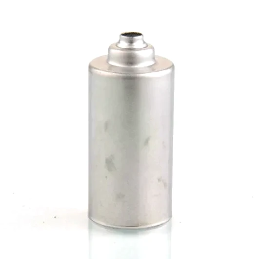
A deep drawn sensor housing contains a sensing element and whatever the element needs around it – a cavity it sits in, a port for the medium to reach it, a route for the leads, and a face that has to be defined precisely because the sensing depends on that face. The housing therefore has two distinct internal requirements that are almost always in conflict: the cavity must be generous and unobstructed for the element, and the sensing face must be exact.
We deep draw the housing and then CNC-finish the critical faces, with first articles verifying the whole flow before the run is released, on deep drawing presses plus CNC turning centres for machined faces, with in-house toolmaking keeping dies and fixtures maintained. Standard stock is carbon steel in SPCC and DC01 grades, 304 and 316 stainless steel, aluminium and brass, with grade and temper confirmed in writing before tooling. Stepped bores run to +/-0.03 mm with concentricity per the print. Design intent is read from the print, and any conflict in the drawing is raised before quoting – which on this part type is exactly the right place to catch the conflicts, because they are usually dimensional and they are usually the drawing’s fault rather than the design’s.
The sensing face is a specification, not a surface
Whatever the sensor measures, it usually measures it at or through a defined face, and that face is where the drawing either succeeds or fails. Four properties, each of which is a separate call:
| Flatness | Determines how the element seats, and whether a gasket or a thermal compound makes continuous contact. A face with a concavity contacts only at its edges and reports a systematically wrong value. Flatness must be measured on its own, not inferred from a dial indicator sweep. |
|---|---|
| Surface finish | A machined face has a lay. Where the face carries a thermal path, the roughness affects contact area and therefore the thermal coupling. Where it carries a gasket, roughness affects compression. The finish is a design variable and should be stated. |
| Position and concentricity | Where the sensing face is also a mounting face or a port face, its position relative to the element cavity and to the port determines where the medium actually reaches. Concentricity of the sensing face to the cavity axis is frequently the dimension that decides whether the part calibrates consistently from unit to unit. |
| Corrosion state of the surface | A machined face is raw metal. If the medium is conductive and the element is insulated from the housing, the surface condition at that face is part of the electrical design, not just the mechanical one. |
And there is a manufacturing consequence that catches people: a machined face has been cut, so it has no coating, no oxide layer, and no plating. Where the part is plated for corrosion, that face is either masked or deliberately left raw. It must be stated, because “plated part” and “plated except the sensing face” are two different parts with two different costs.
The cavity: wall thickness, ribs and the things that happen after drawing
The cavity has the opposite requirement – it must fit the element with enough clearance to assemble and enough stiffness not to move, and its walls must not interfere with the sensor’s field or its optics or its thermal path. Several practical points:
- Drawn cavity size versus finished size. A drawn cavity is controlled by the punch, so its size is a tooling dimension. If the element needs a tight-fitting bore, that bore is machined, not drawn, and the drawing must show the machining allowance in the drawn feature.
- Ribs and bosses inside a drawn part. A rib is easy to form and expensive to form – it needs a matching feature in the die and it changes the die’s ability to release the part. Ribs that hold the element in position are usually better placed in a machined feature or a separate part, because a drawn rib brings its own tolerances into a location that wanted to be precise.
- Draft and release. A drawn cavity must release from the die. The geometry of the element’s pocket therefore has to include draft, and a pocket with square walls in the draw direction may not be drawable at all. This is one of the most common reasons a sensor housing is quoted with a machined pocket instead of a drawn one.
- Draw depth versus wall. A deep draw thins the wall, most at the punch nose, and the thinning is uneven along the length. Where the housing’s wall carries a pressure or carries a thermal gradient, the minimum wall at the punch nose is the design value and the nominal is not.
Ports: how the medium gets in
Every sensor housing has a port, and the port is where the drawing is most often under-specified. The decisions:
- Pierced, drawn or machined. A port in a flat region is pierced. A port in a formed wall is often drawn, which thins the surrounding wall. A port that has to be round, thick-walled or at a precise location is machined.
- Threaded or pressed. A threaded port in sheet needs a boss with enough engagement, or an inserted nut. A press-fit port needs an interference dimension that is specified as an interference, not as a hole size.
- Sealed how? Face seal, O-ring, bonded seal, or a welded fitting. The seal’s requirements feed back into the port’s flatness, bore size and concentricity, so the seal type cannot be an assembly decision made after the part exists.
- Restricted or open? An orifice in a port is a flow restrictor with a calibrated dimension. If the port has a defined restriction, that dimension needs a tolerance tighter than a general hole – and it needs to be stated as a flow or orifice function rather than as a hole.
Materials and the environment the housing lives in
Carbon steel in SPCC and DC01 grades is the cost option for a dry, protected environment and needs plating or coating. 304 stainless steel is the general-purpose choice for a sensor housing and handles both moisture and a wide temperature range; 316 is for chloride-bearing or marine environments. Aluminium is chosen where the housing must be light, where thermal conductivity matters because the sensor is measuring temperature, or where the housing itself is heat-sinked – though a thin-wall aluminium housing is easy to distort during assembly, which matters if it locates the element.
Brass is chosen where the housing carries a machined port, a thread, or a mounting feature – its machinability means the important dimensions can be turned rather than drawn.
Two material-specific things worth raising. First, thermal expansion: a housing that locates a sensing element relative to a duct wall has a gap whose size changes with temperature, and the two materials expand differently – if the element is a temperature sensor, some of that differential expansion becomes measurement error. Second, for a housing in a wet area, the crevice between the sensing face and whatever mounts against it is where corrosion starts, and that interface needs the same coating-versus-masking decision as the face itself.
Where the drawing and the design usually conflict
In our experience the conflicts that get raised before quoting on a sensor housing are consistently the same four, and all four are dimension conflicts rather than concept conflicts:
- The element does not fit the drawn cavity. Usually because the cavity was drawn for nominal size and the element’s tolerance has a minus tolerance on the critical feature. The fix is a machined pocket or a defined local relief.
- The sensing face cannot be both drawn and machined. A drawing that calls for a drawn face and a flatness requirement on that face is asking for two incompatible things; the flatness requirement wins and the face becomes machined.
- Port position and boss position cannot both be true. A boss formed on the port axis moves the wall, and the port’s position follows the boss. One of them has to be the datum.
- Coating on a face that must not be coated. Which is a specification gap rather than a conflict, but it appears on the drawing as a conflict because the finish note and the functional note disagree.
Grade and temper confirmed in writing before tooling, surface treatment matched to the duty with alternatives quoted alongside and samples approved in writing, die cost transparent, and maintenance tracked against the part number. Samples and first articles follow the same discipline: measured, reported, then approved.
The single most useful thing to send with the enquiry, if you have it, is the sensing element’s datasheet or a section drawing showing its mounting envelope and its tolerances. It converts a review into a check.
How a sensor housing is inspected
Because the controlling features are machined and geometric rather than just dimensional, the inspection plan for a housing is worth setting up deliberately rather than accepting whatever falls out of a first-article check. Three things we do on these parts, and the reason for each:
- Bore size and concentricity on the CMM. Stepped bores at +/-0.03 mm are checked for size and, where the print calls for it, for runout against the named datum. Size alone would pass a part that is out of square.
- Face flatness on a surface plate or a CMM scan, not by feel. The flatness of the sensing face determines whether the element seats, and it is the single most common cause of a sensor that reads consistently slightly off. It needs an instrument that reports a number.
- A functional check where the design allows one. On a housing with a defined port restriction or a defined cavity, a simple functional check – pressure decay, flow, or a leak test – catches assembly and sealing problems that no dimensional inspection will find. Where the design permits it, this is worth more than another dimension on the report.
And one reporting point: critical dimensions carry CMM data with the shipment, which is what makes a repeat order verifiable. A housing that has drifted by 0.02 mm on a bore over six months is within tolerance and may still assemble differently; a housing that has drifted is discoverable only if the original data exists to compare against, which is why the approved first article is retained as the gauge reference and later batches are gauged back to the signed sample rather than to a nominal drawing alone.
Sensor Housings is the parent range for parts like this one; the overview page gathers the tooling logic, finishing options and tolerance notes that apply across the family.
Specifications
| Item | Deep drawn sensor housing |
|---|---|
| Brand | AUNOV |
| Designing | Design intent is read from the print, and any conflict in the drawing is raised before quoting. |
| Tooling | Progressive and drawing dies are designed and built in house, so die cost stays transparent, and maintenance is tracked against the part number. |
| Samples | Sample and first article are the same discipline here: measured, reported, then approved. |
| Materials | Standard stock: carbon steel (SPCC / DC01), 304 / 316 stainless steel, aluminium, brass; grade and temper are confirmed in writing before tooling. |
| Surface finish | Plating, coating or polishing to suit the drawing; alternatives quoted with the quotation, samples approved in writing. |
| Processing | After deep drawing, critical faces are CNC finished; the whole flow is verified on first articles before the run is released. |
| Equipment | Deep drawing presses plus CNC turning centres for machined faces, with in-house toolmaking to keep dies and fixtures maintained. |
| Tolerance | +/-0.03 mm on stepped bores, concentricity per print; critical dimensions carry CMM data with the shipment. |
| Delivery terms | FOB Ningbo or Shanghai, T/T with deposit and L/C for larger runs; call-off schedules are supported. |
Frequently Asked Questions
What are the two internal requirements of a deep drawn sensor housing?
The cavity must be generous and unobstructed for the sensing element, while the sensing face must be exact. These usually conflict, and the resolution is read from the print rather than assumed.
Why is the sensing face a specification, not just a surface?
The sensing depends on that face being defined precisely, so it is CNC-finished to stepped bores of +/-0.03 mm with concentricity per the print. A vague face dimension is the usual source of a non-working housing.
Which materials are used for sensor housings?
Carbon steel in SPCC and DC01 grades, 304 and 316 stainless steel, aluminium and brass, with grade and temper confirmed in writing before tooling. The choice follows the medium and the environment.
How is a sensor housing inspected before release?
First articles verify the whole flow – draw, CNC faces, ports and the lead route – before the run is released, and CMM data travels with the shipment. The typical minimum order is 1,000 pieces with a 24-hour quotation.
Related Products
Request a Quote for This Part
Send a drawing or sketch — get material advice, tooling cost and a per-piece price within 24 hours (working days).