

A sensor tube is a mounting datum that happens to be hollow
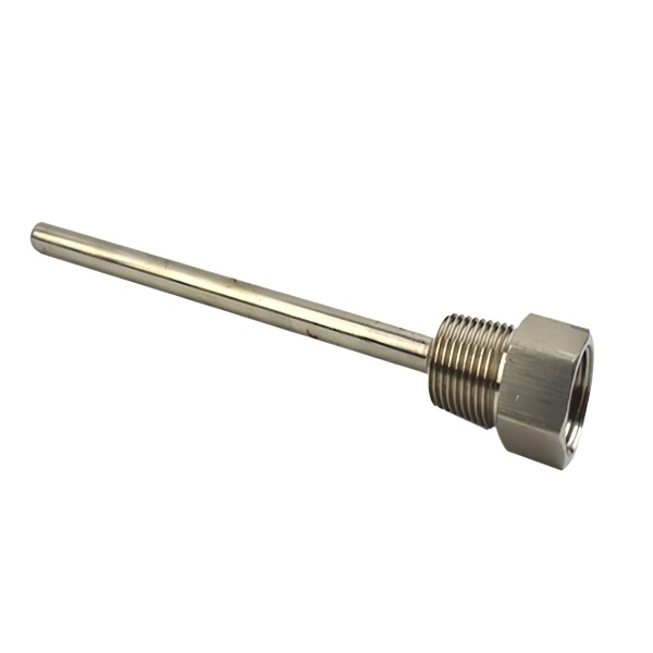
A drawn sensor tube has a deceptively ordinary shape – a cylinder, sometimes stepped, sometimes with a flange, usually hollow. Its function is not structural in the usual sense. Its function is to locate a sensor accurately, to carry the sensor’s leads or its pressure reference, and often to provide the surface that the sensor’s own sealing face presses against. That makes it a precision locating component, and the tolerance that matters is almost never the wall – it is the concentricity of the stepped bores and the flatness of the machined face.
We blank, draw and pierce in sequence and then machine the sealing faces, logging every stage against your part number, on hydraulic drawing presses with CNC lathes for the sealing faces, secondary operations on CNC turning centres, and CMM inspection. Stepped bores are held to +/-0.03 mm with concentricity per the print, and critical dimensions carry CMM data with the shipment. This page covers why concentricity is the controlling feature on a part like this, and how to write a drawing that makes it achievable.
Concentricity: the one number that decides if the part works
Think about what a stepped bore is for. A stepped bore lets a sensor go into the tube to a defined depth, with a shoulder it seats against. If that shoulder is not square to the sensor’s axis, then:
- The sensor does not seat flat – it rocks or sits on the edge of the shoulder, and the gap it leaves is a leak path or a thermal error.
- The sensor’s own axis is tilted relative to the tube’s axis, so any measurement or reference the sensor makes is tilted too.
- On an assembly of several such tubes, the tilt accumulates and the assembled device is misaligned.
This is why the specification calls stepped bores to +/-0.03 mm and carries concentricity as a separate requirement. A bore can be perfectly within size at every depth and still be useless if it is not square to the outside diameter. And a bore can be square to the outside diameter but square to the wrong thing – which is the datum problem.
Three datums, and knowing which one is which
A drawn tube typically has three separate features that could serve as a locating reference, and they are not interchangeable:
- The outside diameter. The part that presses into the sensor housing or the mounting block. Whatever the tube mates into will locate on this, so this OD is the natural primary datum.
- The machined face. The flat that a seal presses against or that the sensor seats against. This is machined after drawing, and it is the surface that has to be square to the bore.
- The stepped bore itself. The feature that locates the sensor axially. This is what has to be concentric with the OD, and concentric to the face.
The design intent needs to be stated, and it is worth stating in a sentence rather than leaving it implicit in the tolerances. Something like “the stepped bore is concentric to the mounting OD within 0.05 total runout, and the sealing face is perpendicular to that bore axis within 0.03” tells a machinist what to build and tells an inspector what to measure. Without it, each shop makes a reasonable assumption and the parts do not interchange.
Runout versus concentricity is worth distinguishing, because the difference matters in practice. Concentricity controls a diameter feature relative to a datum axis. Total runout controls the whole surface including any taper. A drawn OD has a natural taper and a natural ovality from the draw, so a drawn OD is rarely a good datum for a tight total runout control – which is one reason a part like this sometimes gets a short, straight, machined band as its datum rather than the drawn surface.
Drawn tube, machined bore: the process interaction
The route here is blank and draw and pierce, then machine. That order is deliberate and it has consequences worth understanding, because they are the difference between a part that hits concentricity and one that nearly does.
- The drawn bore is not a precision bore. It comes from the punch, so its size follows the punch, and it carries draw marks and a slight taper. Its roundness is good – punch-formed bores are among the best-made round features in stamping – but its size is a tooling dimension, not a finished one.
- Machining the bore removes material asymmetrically. A CNC turning operation that takes a light cut on one side of a slightly oval or slightly off-axis bore removes more on that side and leaves the geometry slightly changed. This is why a bore is best machined in at least two cuts, and why a heavy first cut is a bad idea on a drawn bore.
- Clamping distorts the part. A thin-wall drawn tube clamped in a three-jaw chuck for machining will deform, and it will spring back after release. Where concentricity is tight, the tube is supported by a collet or by a soft jaw profile that follows the tube, and the machining allowance needs to be enough that the distortion is removed rather than locked in.
- Rigid-body geometry must be right before machining. If the drawn tube is out of round or bent, the machining operation cannot produce a concentric result because it is working on a part that is not straight. A straightness or ovality requirement on the drawn section is not cosmetic – it is an input to the machined result.
Materials: what the medium and the temperature actually demand
We hold carbon steel, 304 and 316 stainless steel, aluminium and brass, and material substitutes are proposed only with your written approval – which is the right arrangement on a sensor part, because a substitution that looks equivalent is often not.
| 304 stainless steel | The common choice for a sensor body. Stable, strong, and dimensionally stable at temperature. 316 where chlorides or a wet environment are present. |
|---|---|
| Carbon steel (SPCC / DC01) | Where cost governs and the environment is dry and protected. Needs coating, and the coating has to be specified not to build on the sealing face. |
| Aluminium | Light and thermally conductive – a real advantage where the sensor needs to stay coupled to what it measures. Lower stiffness, and the mounting bore can move with bolt preload. |
| Brass | Machinable to a fine surface, good for threaded and sealed connections. Heavier than aluminium and dimensionally less stable at temperature. |
Thermal expansion is worth mentioning because it affects the whole design, not just the material choice. A sensor tube that locates a sensor relative to a wall has a gap that changes with temperature, and the two materials on either side of that gap expand differently. If the sensor measures temperature, that differential expansion can appear as a measurement error. This is a systems question rather than a drawing question, but it is the reason a sensor assembly drawing usually specifies both parts’ materials rather than leaving the tube as “whatever fits”.
The sealing face, and where the leak path actually is
On a sensor tube the leak path usually runs through the sealing face rather than through the wall. Four things determine whether it seals:
- Flatness of the machined face. A seal needs a continuous contact band. A face with a concavity in the middle will contact only at the edges and leak through the middle – and this is not visible on a first article without a straightedge.
- Surface finish of that face. A turned face has a lay. For an O-ring seal a fine, consistent finish is wanted; for a face-seal joint a slightly controlled finish helps the gasket conform. Either way the finish needs to be specified, and surface roughness and flatness are separate requirements.
- Runout of the face. A face that is flat but tilted relative to the bore will still produce an uneven seal band, because the seal compresses unevenly around the circumference.
- Whether the face is masked from coating. A plated or coated face has a coating thickness between it and the seal. Mask it, or specify that the coating is acceptable there, but do not leave it open.
Getting the drawing right, and what to send
Send drawings, or send a sample to be measured, and a manufacturability review comes back with the quotation. Revisions are re-quoted once rather than silently absorbed. Die design and toolmaking stay in house so die cost stays transparent, and maintenance is tracked against the part number – which on a precision part is worth having, since a worn die on a bore-forming station shows up as a drifting bore size long before it shows up as a complaint.
Sample and first article are the same discipline here: measured, reported, then approved. Five things on the drawing that make a sensor tube achievable and verifiable:
- Which feature is the primary datum – normally the mounting OD.
- What each stepped bore is concentric to, and to what tolerance, expressed as runout against a named datum rather than as a general position.
- Which face is perpendicular to which axis, and by how much.
- Straightness and ovality of the drawn section, since these are the input to the machined result.
- Flatness and finish of the sealing face, stated separately, and whether it is masked from coating.
With those five written down, the part is straightforward to tool, straightforward to make, and straightforward to inspect – and the CMM report that ships with the goods actually demonstrates the thing the drawing asked for.
Our Sensor Housings range is where this part sits. The sensor housings pages carry the process notes, common materials and inspection points behind every product in the family.
Specifications
| Item | Deep drawn sensor tubes |
|---|---|
| Brand | AUNOV |
| Designing | Send drawings, or send a sample to be measured – a manufacturability review comes back with the quotation; revisions are re-quoted once rather than silently absorbed. |
| Tooling | Die design and toolmaking stay in house, so die cost stays transparent, and maintenance is tracked against the part number. |
| Samples | Sample and first article are the same discipline here: measured, reported, then approved. |
| Materials | Materials held include carbon steel, 304 / 316 stainless steel, aluminium and brass; material substitutes are proposed only with your written approval. |
| Surface finish | Duty decides the surface treatment, plating, coating or polishing; we quote alternatives with the quotation and approve samples in writing. |
| Processing | Blanking, drawing and piercing in sequence, then machining of sealing faces; every stage is logged against your part number. |
| Equipment | Hydraulic drawing presses and CNC lathes for sealing faces; secondary ops run on CNC turning centres, inspection on the CMM. |
| Tolerance | +/-0.03 mm on stepped bores, concentricity per print; critical dimensions carry CMM data with the shipment. |
| Delivery terms | Freight, Incoterm and payment term are confirmed on the order: FOB, CIF or DDP, T/T or L/C. |
Frequently Asked Questions
Why is concentricity the controlling tolerance on a sensor tube?
A stepped bore lets the sensor enter to a defined depth and seat against a shoulder. If that shoulder is not square to the sensor’s axis, the sensing element sits tilted in the tube and the part stops doing the one job it exists for, which is holding that element on the datum.
Can you hold concentricity on a deep drawn tube?
Yes, because the geometry that sets the axis is not left to the draw. We blank, draw and pierce in sequence and then machine the sealing faces and bore, so those features are cut after drawing. Stepped bores are held to +/-0.03 mm with concentricity to the print, and critical dimensions ship with CMM data.
How should we write the datums on the drawing?
A part like this has three plausible datums and the drawing has to say which is which, because the machine can only hold the relationships it is told to hold. Take the datum from the feature the assembly actually locates on, not from the one that is easiest to measure.
Where does a sensor tube actually leak?
Almost never through the wall, and almost always through the sealing face. The seam-free drawn body has no leak path of its own, so flatness, finish and fastener pattern at the sealing face are what earn or lose the seal.
Related Products


Request a Quote for This Part
Send a drawing or sketch — get material advice, tooling cost and a per-piece price within 24 hours (working days).