
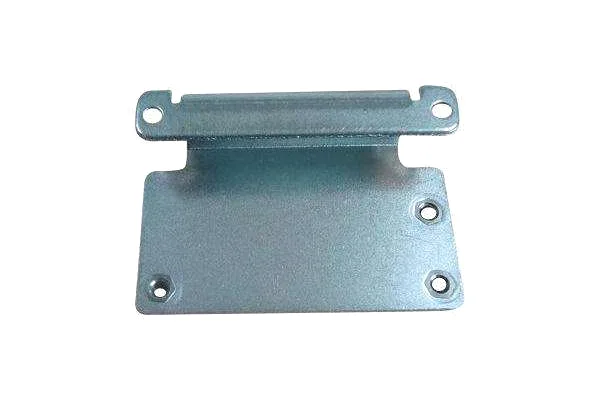
A clip bracket is a spring that has to be right the first time
A galvanised stamped clip bracket holds something by being bent, and that single fact makes it the least forgiving part in the stamping family. A structural bracket can be off by a fraction and still work. A clip bracket that is slightly too stiff will not assemble, and one that is slightly too soft will not hold – and because it is a spring, both of those outcomes are governed by material properties that are not fully known until the material is in the press.
We die-stamp these with in-press forming and piercing, logging every stage against your part number, on 5-250 T mechanical presses with dedicated dies and in-house toolmaking to keep dies and fixtures maintained. Pierced holes are held to +/-0.03 mm and formed sections to +/-0.1 mm, and dimensional reports accompany the first article. Finish thickness and adhesion are checked on the first article. This page is about the four variables that set a clip’s behaviour, and about how to specify a part whose whole function depends on all four.
Clip force is an output, not a drawing dimension
A clip bracket generates a force by being deflected. The force depends on the section’s geometry and the material’s properties, and because the part is often specified as a bracket with a clip on it, the force requirement is often the one thing that was never written down. Four variables decide it:
- Material grade and temper. The elastic modulus is nearly the same across steels, but the yield strength is not – and a spring works elastically, so it is limited by yield, not by modulus. A low-carbon annealed strip and a half-hard or full-hard strip of the same dimensions can differ in clip force by a factor approaching two, because the lower-strength material simply yields and stops. This is why grade and temper must be confirmed in writing before tooling.
- Section thickness. Clip force scales with thickness cubed for a beam in bending. This is why a 0.1 mm error in thickness specification on a clip part is not a small error.
- Section width and length. Width scales force linearly; deflection scales with the cube of length. A clip 10% longer is about 27% weaker and deflects about 33% further.
- Width of the load-bearing section at the bend. The force is concentrated where the clip bears against the housing. A narrow waist at the bend is a deliberate and effective way to tune the force without changing thickness.
Which means a clip bracket drawing that states only the outline is not a complete specification. It should state the required retention force or deflection, the material in a defined condition, and the thickness with its tolerance in the springing area. With those three, a clip can be designed and repeated. Without them, it can only be sampled.
Galvanising changes the part, not just its appearance
Hot-dip galvanising is specified on these brackets for corrosion resistance, and it is a good specification for exposed steel in a wet or industrial atmosphere. It also does four things that need to be designed for rather than discovered afterwards.
- Coating thickness adds to every dimension. A typical zinc coating on a small stamped part adds measurable material on both faces and around every edge. A pierced hole becomes smaller by twice the coating thickness. Where a hole is at a limit, this matters; where a hole is a clearance hole, it rarely does.
- Edges and corners build up more than flats. Galvanising runs build on edges and inside corners – which is exactly where a clip’s bearing contact is. A galvanised clip can feel different in the hand and can wear differently against a housing than an unpainted one.
- Flow marks and dross. The classic galvanising appearance is the zinc-iron crystal pattern, and it is a genuine cosmetic acceptance question. Parts that are visible need the finish appearance written down, not assumed.
- It changes dimensions at tolerance level. Where a clip engages with a mating feature, the coating needs to be either included in the design clearance or excluded from the tolerance stack. This must be stated on the drawing – typically “coating not included in dimensions”.
Electroplating is the alternative where dimensional stability matters more than coating thickness, because plating can be controlled to a tighter and more uniform thickness. Zinc flake and zinc-aluminium systems offer better crevice corrosion resistance than conventional plating, at a different appearance. For a clip that goes into a wet cavity with other galvanised or plated fasteners, matching systems matters for galvanic compatibility – dissimilar metals in an electrolyte create a galvanic cell, and the clip is often the small part that corrodes as a result.
Defining and locating the clip
The clip does two distinct jobs on most brackets, and it needs two distinct definitions, which drawings frequently combine into one ambiguous note:
| Retaining clip | Holds a component in place against an upward load. Must not release. The definition needed is a retention force in the installed condition, or a deflection at a stated load. |
|---|---|
| Locking clip | Prevents a fastener from backing off. The definition needed is an interference with the fastener, and it is set by hole size and coating – so the fastener specification and the clip specification are the same specification. |
| Detent or indexing feature | Provides a defined number of positions. The definition needed is the force profile through the travel, because a detent that is easy to enter and hard to leave is not a detent. |
Whatever the type, the hole through which the fastener passes is the tightest tolerance on the part and we hold pierced holes to +/-0.03 mm here. That figure exists because a clip’s function depends on its hole size directly. The drawing should also state whether the hole is the controlling dimension before or after coating – and for a locking clip it is normally the size after coating, since that is the size the fastener sees.
Springback in a clip is worse than in a bracket
A bracket that springs back is off by an angle. A clip that springs back is off by a force, and the force error can be large because the free length of the clip is short. A clip that deflects 2 mm on a 12 mm free length is working at a strain where springback is not a small effect – the part will be permanently set, and the retention force will drift downward over the first few cycles and then stabilise at a lower value.
Managing this:
- Over-bend deliberately and compensate in the die. For a spring clip this is the normal method rather than an exception, because the compensation is a large fraction of the angle.
- Specify a material in a defined temper and hold it to it. The most effective control on a clip is not the die – it is the material. The spring property of the strip is what everything else is compensating for.
- Set the clip through its working deflection once before shipping. Where the retention force is critical, pre-cycling the clip stabilises it. This is a real production step and it should be a documented one, because a pre-cycled clip and a fresh clip do not have the same force.
- Measure force, not just dimension. A go/no-go gauge for the clip is worth more than any dimensional report on this part type. Our in-house toolmaking produces the gauges as well as the dies, so the gauge and the part are controlled on the same system.
Getting from a sample to a controlled drawing
Many clip brackets arrive as a sample with a note. The route that works is to reverse-measure the sample into a controlled drawing, and the same drawing is then used for every repeat order. Three things need to come out of that measurement explicitly, because none of them can be recovered later from a physical sample:
- The material, stated with grade and temper. Measured from the sample where possible, confirmed with the customer in writing, and then fixed in the purchase specification. This is the single highest-value item on the drawing for a spring part.
- The springing-section thickness, as-found. Not the nominal material thickness – the measured thickness in the clip area, which is what the force is calculated from.
- The functional requirement in force or deflection terms. Without this the drawing describes a shape and not a function, and every repeat order is a fresh experiment.
Carbon steel in SPCC and DC01 grades, 304 and 316 stainless steel, aluminium, brass and copper are all held, with the grade matched to the duty. Stainless Steel is the choice where corrosion or a non-magnetic requirement dominates, with the note that a stainless steel clip will not take a plating the way steel does and its spring properties differ. Aluminium clips are light and corrosion-resistant but have a lower modulus and a lower fatigue limit, so a steel clip and an aluminium clip of the same shape are not interchangeable on force or life. Brass and copper are used where conductivity or a specific media compatibility applies.
Commercial terms
Every stage is logged against your part number, dies and fixtures and gauges are made in our own toolroom so tooling lead time stays under our control, and the die remains dedicated to your part. Dimensional reports accompany the first article, and finish thickness and adhesion are checked on it. Delivery terms, Incoterms and payment terms are as quoted, with repeat orders running against the same controlled drawing and the same approved first article – which on a clip bracket is the reference that keeps the force consistent, and therefore the reference worth protecting.
Custom Metal Stamping Parts is the parent range for parts like this one; the overview page gathers the tooling logic, finishing options and tolerance notes that apply across the family.
Where this part is used
A clip bracket holds something by being bent, which makes it the least forgiving part in the stamping family. A structural bracket can be off by a fraction and still work; a clip bracket that is slightly too stiff will not assemble, and one that is slightly too soft will not hold. Because it is a spring, both of those outcomes are governed by material properties that are not fully known until the material is in the press, and the galvanising step changes them again.
You will find clip brackets in panel and enclosure assemblies, in appliance and furniture hardware, in automotive trim and battery retention, and in the covers and guards that have to stay put without a fastener. Wherever the clip replaces a screw, the economics are the point – a snap-fit costs nothing to assemble and nothing to service – but that economics depends entirely on the clip being right, and a bracket that fails to engage stops a line.
What we need to quote it
Send the clip’s section geometry and the material grade and temper confirmed in writing, plus the deflection or force requirement in whatever form you have it – a force in newtons, or a gap the clip has to close, or a sample you want matched. The force requirement is usually the one thing that was never written down, so it is worth stating even approximately. Tell us whether the part is galvanised, and whether it is the hot-dip or the electro type, because the two change the part very differently.
Specifications
| Item | Galvanized Stamped Clip Bracket |
|---|---|
| Brand | AUNOV |
| Designing | Your drawing sets the part – samples are reverse-measured into a controlled drawing; the same drawing is used for every repeat order. |
| Tooling | Dies, fixtures and gauges are made in our own toolroom, so tooling lead time stays under our control, and the die remains dedicated to your part. |
| Samples | Prototype and pre-production samples are provided against the drawing, so any deviation is corrected at sample stage, and mass production is gated on that approval. |
| Materials | Carbon steel (SPCC / DC01), 304 / 316 stainless steel, aluminium, brass and copper – the grade is matched to the duty of this bracket. |
| Surface finish | Plating, coating or polishing to suit the drawing; finish thickness and adhesion checked on the first article. |
| Processing | Die stamping with in-press forming and piercing; every stage is logged against your part number. |
| Equipment | Press shop with 5-250 T mechanical presses and dedicated dies, with in-house toolmaking to keep dies and fixtures maintained. |
| Tolerance | +/-0.03 mm on pierced holes, +/-0.1 mm on formed sections; dimensional reports accompany the first article. |
| Delivery terms | FOB, with DDP offered for EU and US addresses, payment by T/T or L/C, quoted in USD or EUR; repeat orders reuse the approved first article. |
Related Products



Request a Quote for This Part
Send a drawing or sketch — get material advice, tooling cost and a per-piece price within 24 hours (working days).