
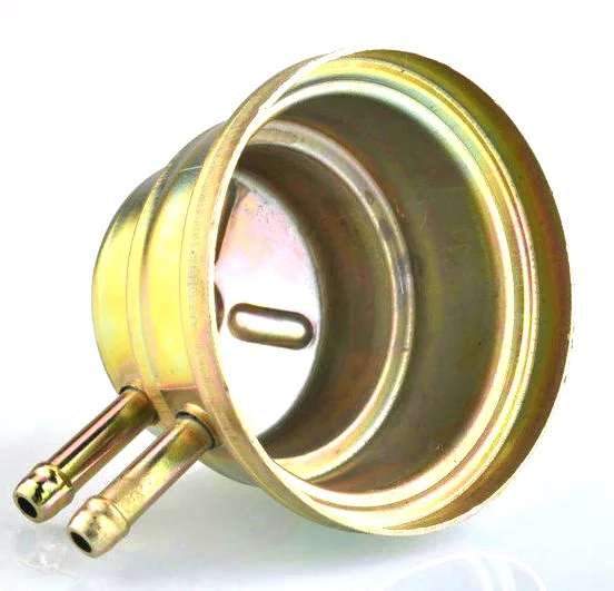
The side hole is the feature; the cap is the consequence
Ask why a stamped end cap needs a hole in its side wall and the answer changes what the cap should look like. A hole in a cylindrical cap is not a decoration and not a convenient place for a fitting. It is a deliberate opening that serves one of four jobs, and each job puts a different set of demands on the cap’s geometry, its wall thickness, and the process route used to make it.
| Vent / equalisation | Makes the internal volume of the cap breathe with ambient so that a sealed assembly does not build pressure or vacuum. Small, deliberately sized, and usually fitted with a hydrophobic or labelled vent. |
|---|---|
| Pressure equalisation port | Carries fluid between two chambers so they cannot trap differential pressure. Frequently a larger port with a fitting, gasket or welded tube attached. |
| Drain or bleed | Discharges condensate or air from a low point. Position matters more than size – it has to be at the bottom of the installed orientation, which is not necessarily the bottom of the cap as it is stamped. |
| Access port | Lets something be installed, removed or inspected without opening the housing. Usually the largest hole of the group and the one that most affects the cap’s stiffness. |
Once the function is named, the rest follows. A vent hole wants a hole that is small, round, burr-controlled and located on a flat enough area that a vent part seats flat against it. An access port wants a flange. And every one of them competes with the cap’s job of closing an end – which is why the process route matters as much as the drawing here.
How the cap is made, and what that does to the hole
This cap is blanked and progressively formed on automated lines, then finished with secondary tapping, bending and finishing operations. Mechanical presses from 5 to 250 T and hydraulics from 250-500 T are available, with in-line annealing. Drawn sections run at +/-0.1 mm general, machined seats at +/-0.03 mm.
The sequencing decision that most affects a side hole is whether it is pierced before or after the cap wall is formed. Piercing in the flat blank is the accurate way – the hole position is set in two dimensions where the tooling is most rigid, and there is no forming distortion to add to it. Piercing after forming means piercing a cylindrical or cupped wall, which is a different operation: the punch sees a curved, work-hardened surface, the hole tends to become slightly oval and slightly out of square to the wall, and the burr side is no longer under simple control. Where the hole has a functional tolerance – a vent that must seat, a port that must align with a tube – pierce-in-the-flat is worth the extra station.
Two further points on the hole itself. First, burr orientation: the punch side determines which face carries the burr, and on a cap that goes into a housing the choice can be dictated by clearance rather than by preference. Second, hole position relative to a formed feature: if the hole is placed near the cap’s rim curl or a drawn step, the forming of that step will move material and the hole’s position will follow. Locating the hole in a plain wall region, clear of forming features by at least the punch diameter plus a reasonable edge distance, avoids the problem.
Stiffness: a hole is a stress concentrator in a shell
An end cap’s structural job is to resist pressure or vacuum differential and to resist being knocked. A hole in a cylindrical wall interrupts the load path exactly where the hoop stress runs, so the cap around the hole is the first place to look when a cap deforms permanently or cracks.
The measures that matter, roughly in order of how much they help:
- Reinforce locally. A drawn or embossed boss around the hole restores most of the interrupted section and gives the hole something to seal against. This is the standard solution and it costs one extra forming station.
- Keep the hole away from the peak hoop stress. Hoop stress peaks at the rim of a cylindrical or domed cap, so a hole in the flat centre of a dished cap is far less loaded than a hole near the edge – even though they are the same diameter.
- Use the wall thickness you have, honestly. Around a hole the effective section is reduced by the hole diameter; a hole that removes a quarter of a wall’s section has to be treated as a quarter less material at that point.
- Control the edge quality. A hole edge is a fatigue initiation site. The burr side, the break from piercing, and any grinding need to be specified where the load is cyclic.
For a genuinely high-pressure cap, the pressure differential and the cycle rate together define the required wall, and a calculation is worth doing rather than assuming the drawn wall is enough. We check first articles on the CMM and provide mill certificates and heat numbers with the first article, so the material behind the calculation is traceable.
Sealing the hole: what closes it in service
The cap’s side hole is nearly always filled by something, and the options each impose their own requirement on the drawing:
- Tapped hole with a fitting screwed in. Requires enough thread engagement to resist being tightened repeatedly without stripping. In sheet, that means either a thicker wall, a drawn boss, or an inserted nut – and the drawing must state which, because an unspecified tapped hole in 1.2 mm sheet is not a design.
- Welded fitting or tube. The most reliable permanent joint, and it adds a welding operation whose heat input can distort the cap – another reason to keep the hole away from tight flatness requirements, or to plan the sequence so welding happens before the final forming and sizing.
- Adhesive or sealant. Acceptable on a low-pressure or non-structural port, and it depends entirely on surface preparation and cure time. The cap’s surface finish specification and the sealant supplier’s preparation requirement have to agree.
- Left open as a vent. Then the specification is the hole size and its location, plus a burr condition. An open vent on a housing that eventually gets painted or coated is a decision that has to be made at quotation, because coating the vent would defeat it.
Surface finish on the cap is plating, powder coating, anodising or polishing per the print, and it is inspected together with the dimensional report on the first article. If a face is masked for plating, say so on the drawing and it will appear on the quotation.
The machined seat, and why it changes the route
Where the cap has a machined seat, the part is no longer a pure stamping. Secondary operations run on CNC turning centres, which is where the +/-0.03 mm band comes from. A machined seat exists for a reason – it needs to be a bearing surface, a register for another part, a valve seat, or a location that has to be concentric with the cap axis. Those are the jobs a stamped surface cannot do reliably.
Two practical consequences. First, the machining has to be planned around the forming: holding a thin stamped cap in a fixture to machine a face is a fixturing problem, and the part’s own flatness is what determines whether the face runs true. Second, the machining allowance has to be designed in. A stamped face carries drawing marks, an oxide skin and a general dimensional band of +/-0.1 mm; a design that expects to take 0.3 mm off a stamped face to reach a machined tolerance must say so, or the machined seat ends up short.
In-house toolmaking keeps the dies and fixtures maintained, and the tooling record travels with the part number so maintenance history is never lost – which matters on a part like this, where a dull piercing punch would show up as a vent hole that has quietly grown in diameter.
Review notes and commercial terms
Send drawings, or send a sample to be measured. DFM notes come back before any tooling is cut, and changes are priced before they are made – the questions worth answering early are what the side hole is for, what closes it, what pressure or differential the cap sees, and whether any face of the cap has to be machined and therefore what the stamping has to leave behind.
Sample parts are measured and reported before submission; the sample is retained as the master, and production starts only after written sign-off. Standard stock is carbon steel in SPCC and DC01 grades, 304 and 316 stainless steel, aluminium and brass. Delivery is FOB Ningbo or Shanghai with T/T, L/C at sight or D/P, and each volume tier carries its own quoted price – reasonable for a cap whose tooling is modest and whose real economics sit in the secondary operations.
Our deep drawn covers guide puts numbers to the design decisions behind a part like this — draw ratio, wall thinning, radii and trim; the Precision Deep Drawn Parts pages collect the rest of the family.
Specifications
| Item | Stamped End Cap with Side Hole |
|---|---|
| Brand | AUNOV |
| Designing | Send drawings, or send a sample to be measured – DFM notes are returned before any tooling is cut; changes are priced before they are made. |
| Tooling | The tooling record travels with the part number, so maintenance history is never lost. |
| Samples | Sample parts are measured and reported before submission, so the sample is retained as the master, and production starts only after your written sign-off. |
| Materials | Standard stock: carbon steel (SPCC / DC01), 304 / 316 stainless steel, aluminium, brass; mill certificates and heat numbers accompany the first article. |
| Surface finish | Plating, powder coating, anodising or polishing, per the print; the finish is inspected with the dimensional report on the first article. |
| Processing | Blanking and progressive forming on automated lines, then secondary tapping, bending and finishing. |
| Equipment | Mechanical presses from 5 to 250 T and hydraulic presses 250-500 T, with in-line annealing furnaces; secondary ops run on CNC turning centres, inspection on the CMM. |
| Tolerance | +/-0.1 mm general on drawn sections, +/-0.03 mm on machined seats; GD&T per drawing, PPAP-style reports on request. |
| Delivery terms | FOB Ningbo or Shanghai, payment by T/T, L/C at sight or D/P; each volume tier carries its own quoted price. |
Frequently Asked Questions
Why do you ask what the side hole is for before quoting the cap?
Because the hole dictates the geometry, the wall thickness and the process route. A vent wants a small, round, burr-controlled opening on an area flat enough for a vent part to seat against, an access port wants a flange, and every one of those competes with the cap’s original job of closing an end.
How is the hole stopped from weakening the shell?
By treating it as a deliberate stress concentrator rather than a removed piece of metal. The surrounding shell is laid out so stiffness survives the opening, and any feature that has to sit in the hole is given enough flat land to seat on.
Does the hole need sealing, and who decides how?
Sealing follows from which job the hole does, so it is chosen at design time rather than added later. A vent and a port close in different ways, and neither should be selected after the cap has already been routed.
Does this cap need machining?
A machined seat changes the route, and it earns its cost wherever something has to seal against a true face rather than against a formed surface. It is a drawing decision, because relying on the as-formed wall to seat usually costs more later than machining costs now.
Related Products


Request a Quote for This Part
Send a drawing or sketch — get material advice, tooling cost and a per-piece price within 24 hours (working days).