
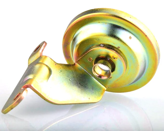
The housing is part of the magnetic circuit
Most housings on this site are structures or covers – they hold something and keep dirt out. An electromagnetic switch housing is different: in a solenoid, a contactor or a relay, the drawn steel shell is the flux return path. The coil pushes flux through the plunger, and that flux has to come back somewhere; a well-designed switch routes it back through the housing wall rather than through air. That single fact changes how the housing must be designed, made and inspected, because now the wall thickness, the steel grade and the concentricity of the bore are electrical parameters, not just mechanical ones.
We draw these housings for starter solenoids, contactors and similar electromagnetic devices, and this page covers what makes them different from an ordinary deep-drawn can.
Steel grade is an electrical choice
Not every steel conducts flux equally well, and for a switch housing the two figures that matter are permeability and saturation flux density. Low-carbon steel in the annealed condition has high permeability and carries the working flux with little loss; the same steel heavily cold-worked by a deep draw has lower permeability because the deformation disrupts the grain structure, and a housing made that way will need more coil current for the same pull-in force. The practical consequences:
- Grade selection settles at a low-carbon drawing-quality steel, chosen for magnetic performance as much as for formability.
- Annealing after forming is usually specified, because it recovers the permeability that the draw destroyed. For a switch that runs at a low duty cycle an anneal may be optional; for one that must pull in reliably on a weak battery, it is not.
- Wall thickness sets the flux-carrying cross-section. A wall that is too thin saturates and the switch becomes weak and slow; a wall that is thicker than needed wastes material and money.
We agree the grade and the anneal condition with the electrical engineer rather than defaulting to the cheapest drawable steel, because a housing that shorts the magnetic circuit is a switch that will not meet its pull-in specification.
The plunger bore: where concentricity becomes force
Inside the housing a plunger travels, and around the plunger there is a working air gap. Everything about that gap – its size, and how evenly it is distributed around the plunger – comes from the housing. Two dimensions dominate:
- Bore diameter and its roundness. An oval bore gives a gap that is wide on two sides and tight on the other two, which both wastes flux and risks the plunger rubbing.
- Concentricity of the bore to the seating face and to the housing axis. If the bore is offset, the plunger is pulled sideways as well as along its travel, which shows up as a weak or noisy operation and as wear on one side of the bore.
We hold the bore by drawing it to a controlled diameter and, where the print demands it, by a sizing pass, then verifying roundness and concentricity on the CMM. For a part whose whole job is to make a plunger move cleanly, the bore is the critical feature and we treat the rest of the drawing as secondary to it.
The seating face and the working air gap
When the plunger completes its stroke it strikes a seat – usually the inside of the housing end or a pole piece. That seat is part of the magnetic circuit and its flatness and height set the residual air gap in the energised position, which in turn sets the hold force and the current the coil draws while held. A seat that is domed leaves a large residual gap and the coil runs hot; a seat that is coined flat holds the designed gap and the coil is efficient. Where the print calls for it, we coin the seat face in the final station so it is flat and its height is controlled, and we check that height on the first article because it is easy to measure and it predicts the electrical behaviour.
Coil cavity, insulation and terminals
A solenoid housing also has to contain a coil and bring its wires out. That raises three questions the housing answers:
- Cavity size. The bore and the end features have to leave room for the coil former and its insulation, with a wall thin enough for a good magnetic path but thick enough to be drawn. We size the cavity from the customer’s coil data, not by eye.
- Insulation and creepage. The housing is metal and grounded, so the coil’s enamel and any liner must be able to withstand the supply voltage indefinitely; the housing’s inside surface is kept burr-free so it cannot cut the enamel or the liner.
- Terminals. Where the coil connects through the housing, the feed-through opening is sealed and the terminal is anchored so that the connecting force is carried by the housing and not by the coil wire.
Closing the housing: crimp, weld or roll
An electromagnetic switch housing is usually closed around its contents, and the closure method affects both the magnetic circuit and the sealing:
| Crimped end | A folded lip clamps the end plate or washer. Fast and cheap, and it gives metal-to-metal contact that carries flux if the crimp is tight. |
|---|---|
| Rolled seam | Used where a longer shell is closed at one end; keeps the wall continuous so the flux path is uninterrupted. |
| Welded end cap | Strongest seal against the engine bay, with the cap welded to the shell so the flux crosses the weld. Weld quality must be controlled so the joint does not become an air gap. |
The trap with any closure is a joint that looks solid but leaves a thin air gap, because a small gap in a magnetic joint is a large reluctance and it weakens the switch. We keep the mating faces clean and, where flux must cross, we press the joint rather than relying on a painted or plated surface to conduct.
Engine-bay sealing
A starter solenoid lives low in the engine bay, where it meets oil mist, road spray, steam from a wash and long periods of engine heat. Water inside the housing corrodes the plunger and the seat and changes the air gap; oil inside cooks onto the coil and insulates the seat. So the housing is closed against both, the plunger passes through a seal or a deliberately generous clearance with a drain, and the terminal opening is sealed. We form a proper seal land at any opening, and where a plunger passes through we agree the sealing scheme with the customer, because a stuck plunger is a no-crank failure.
A switch housing’s wall is sized by its magnetic cross-section
- Diameter: 18-70 mm.
- Length: 20-110 mm.
- Wall: 0.8-2.5 mm, sized for the magnetic cross-section.
- Features: plunger bore, coined seating face, coil cavity, terminal feed-through with seal land, crimp or weld closure, mounting flange.
Annealing for magnetic performance, where the duty calls for it
Do you anneal the housing for magnetic performance? Where the print or the electrical duty calls for it, yes – the draw lowers permeability and the anneal recovers it, and we agree the condition with your electrical engineer.
How tight is the plunger bore? Bore diameter, roundness and concentricity to the seat are treated as one critical group and verified on the CMM; the size is set from your plunger and the air gap you want.
Does the closure affect the switch? Yes – a joint that is not pressed tight becomes a reluctance gap and weakens pull-in, so we control the closure faces, not just the seam appearance.
Can you supply the housing with the coil cavity sized to our coil? Yes, give us the coil former dimensions and the voltage and we size the cavity and the wall for both the winding and the flux.
Specifying an electromagnetic switch housing
Tell us the device – starter solenoid, contactor or relay – the coil voltage and duty, the pull-in and hold force required, the plunger diameter and desired air gap, the closure and sealing needs, and the mounting. Those inputs decide the steel grade, the anneal condition, the wall for the magnetic cross-section, the bore tolerances and the closure method – which is what turns a drawn can into an electromagnetic switch that pulls in every time.
If you are weighing drawing against machining or welding for this geometry, the guide to deep drawn covers sets out where each route wins; the full Precision Deep Drawn Parts range is linked from the overview page.
Specifications
| Item | Electromagnetic switch housing – deep drawn |
|---|---|
| Brand | AUNOV |
| Designing | Files reviewed in PDF, DWG, STEP or IGS; the signed-off revision is the reference for production. |
| Tooling | Dies, fixtures and gauges are made in our own toolroom, so die cost stays transparent, and the die remains dedicated to your part. |
| Samples | Prototype and pre-production samples are provided against the drawing, so any deviation is corrected at sample stage, and mass production is gated on that approval. |
| Materials | Stock covers carbon steel (SPCC / DC01), 304 / 316 stainless steel, aluminium and brass; material substitutes are proposed only with your written approval. |
| Surface finish | Zinc, nickel or chrome plating, anodising, passivation or e-coat; masking and laser marking available where needed. |
| Processing | Coil blanking and progressive drawing, coining on the final station where the print calls for it; every stage is logged against your part number. |
| Equipment | 5-250 T mechanical presses, 250-500 T hydraulic presses and annealing furnaces in line; secondary ops run on CNC turning centres, inspection on the CMM. |
| Tolerance | +/-0.05 mm on drawn diameters, tighter bands confirmed against the drawing; finer bands confirmed from capability data before quoting. |
| Delivery terms | CIF or DDP, with FOB available, payment by T/T or L/C, quoted in USD or EUR; price breaks tie to annual volume. |
Frequently Asked Questions
How is this housing different from an ordinary drawn can?
The drawn shell is part of the magnetic circuit. The coil pushes flux through the plunger and that flux has to return somewhere, so the housing wall carries it rather than air. That single fact makes wall thickness, steel grade and bore concentricity electrical parameters instead of only mechanical ones.
Why does the steel grade become an electrical decision?
Because the permeability of the return path directly affects the force the device develops. Selecting the grade on cost or formability alone can quietly cost performance, so the grade is chosen for the magnetic duty and then checked against the draw.
Why does bore concentricity matter so much here?
Concentricity becomes force. An off-axis plunger bore turns magnetic pull into side load, which shows up as binding or as force that drifts from unit to unit rather than as a dimension anyone measures.
Why would this housing need annealing after forming?
Where the duty calls for it, annealing restores the grain structure that predictable magnetic behaviour depends on. Forming leaves the metal work-hardened, and on a flux-carrying part that condition is a performance variable rather than a mechanical detail.
Related Products



Request a Quote for This Part
Send a drawing or sketch — get material advice, tooling cost and a per-piece price within 24 hours (working days).