
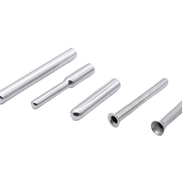
The Stainless Steel Sleeve Tubes with Reduced-Diameter Tips are sensor sleeves whose working end is necked down to a smaller diameter than the body of the tube. The reduced tip is a deliberate design choice: a smaller tip reaches into a space the full-diameter body cannot, presents less frontal area to a flow, and puts less metal at the sensing end so the sensor responds faster. But a reduced tip is also a reduced-strength feature – it necks the tube at exactly the point that has to survive insertion, handling and pressure – and the transition from the full body down to the reduced tip is a stress concentration and a forming challenge. This page covers why the tip is reduced, the transition that gets it there and the strength the reduced section has to keep.
A reduced tip reaches further and responds faster
Two reasons drive a reduced-diameter tip, and both are about the sensing end doing its job better. A smaller tip fits into a space the full body cannot reach, which matters when the measurement point is in a narrow bore, a tight gap or a small passage. And a smaller tip carries less metal at the sensing end, so there is less material to heat up and the sensor responds faster. The reduction is therefore a performance feature, chosen to reach the measurement point and read it quickly, not a styling detail.
- The reduced diameter is chosen so the tip reaches the measurement point the full body cannot.
- Less metal at the tip means faster response, so the reduction is held to a diameter that serves the thermal path.
- Where the reduced tip also has to clear a passage, its diameter is checked against that clearance, not just against a nominal.
The transition from body to tip is a stress concentration
Where the full-diameter body steps down to the reduced tip, the geometry changes abruptly, and an abrupt change in a loaded tube is a stress concentration. If the transition is a sharp shoulder, stress piles up there and the tube is far more likely to crack or fatigue at the neck than anywhere else. The transition is therefore a designed feature with a controlled radius or taper, held where the tube sees load, and it is inspected because it is the point the reduced-tip sleeve is most likely to fail.
- The body-to-tip transition carries a defined radius or taper, because a sharp shoulder concentrates stress at the neck.
- Wall thickness at the transition is measured, because the reduction thins the section exactly where the geometry changes.
- The transition is inspected for the start of any crack, since the neck is where a reduced-tip sleeve fails first.
The reduced tip is the weakest section, and it has to hold
Everything the sleeve has to survive – insertion force, handling, internal pressure, vibration – is now carried by the smallest cross-section of the tube, which is the reduced tip. A tip that is reduced too far, or with too thin a wall, is a tip that bends, buckles or bursts under loads the full body would have taken easily. The reduced diameter and its wall are therefore a strength calculation, not just a reach-and-response choice, and the minimum section is held against the worst load the tip will see.
- Wall thickness of the reduced tip is held against pressure and insertion load, because it is the minimum section of the tube.
- The reduced diameter is capped so the tip still has enough section to survive the handling and pressure it will see.
- Where the tip is pushed into resistant material, its strength is checked against that insertion duty, not just against internal pressure.
Producing the reduction without distorting the bore
The reduced tip is produced by necking, swaging or turning the end down, and on a thin-walled sleeve any of those can distort the bore if the wall is squeezed or stretched unevenly. A reduced tip whose outside is correct but whose bore has gone oval is a tip that seats the sensor badly, and on a thin wall the outside and the bore share so little material that they distort together. The reduction is therefore done with the bore supported or with a controlled process that keeps it round.
- The reduction is made over a supporting mandrel or with controlled tooling that does not squeeze the thin wall oval.
- Bore roundness is verified at the reduced tip, because the sensor seats and reads from the bore, not the outside.
- The reduced tip is held concentric to the body, so the tip lines up with the axis the sensor and the assembly expect.
How we verify a sleeve tube with a reduced-diameter tip
Verification checks the reduced tip, the transition and the concentricity to the body, because the reduced section is where the sleeve is weakest and most likely to fail.
- Reduced tip: diameter, wall thickness and bore verified, since the tip is the minimum section and the sensor seats in its bore.
- Transition: radius or taper confirmed, wall thickness at the neck measured, and the transition inspected for cracking.
- Concentricity: the reduced tip checked to run true to the body axis, so the tip lines up with the assembly.
- Strength: the minimum section confirmed against the insertion, handling and pressure loads the tip will see.
- Bore and seating: bore diameter, roundness and finish confirmed along the tip and body, with sensor-seating position verified.
- Material certificate and fit check: stainless steel grade confirmed per lot, and the sensor inserted and the tip seated in its passage before the run.
First articles and retention samples are kept for the programme, so a repeat run of the reduced-tip sleeve is necked and verified to the same tip and transition. On a part whose reduced tip both reaches further and responds faster but is also its weakest section, holding the tip, the transition and the concentricity to a verified baseline is what keeps a second batch reaching and reading as reliably as the first.
You will find this part in our Sensor Housings range. Process notes, common materials and inspection points for every product in the family are collected across the sensor housings pages.
Specifications
| Item | Stainless Steel Sleeve Tubes with Reduced-Diameter Tips |
|---|---|
| Brand | AUNOV |
| Designing | Send the drawing, or a tube sample we can measure, our engineers reply with a manufacturability assessment and pricing. |
| Tooling | Every die designed and built in our toolroom, held under your part number. |
| Samples | Sample parts arrive with a full dimensional report and material certification. |
| Materials | 304 / 316 stainless steel is the primary stock for this part, alongside carbon steel (SPCC / DC01), aluminium, brass and copper, with grade selection confirmed at drawing review. |
| Surface finish | Surface treatment per the drawing: plating, e-coat, powder coating, anodising, passivation, per your print. |
| Processing | Progressive deep draw stages with in-line annealing as the draw ratio demands, pierced and machined on the same floor. |
| Equipment | Press capacity from 5 to 500 T across mechanical and hydraulic lines, in-house CNC cells and a temperature-controlled inspection room. |
| Tolerance | +/-0.1 mm as-drawn, machined features held to +/-0.03 mm. |
| Delivery terms | FOB is standard; DDP offered for EU and US, T/T and L/C accepted, D/P for established customers, call-off schedules supported. |
Frequently Asked Questions
Why reduce the tip rather than simply use thinner tube throughout?
The two ends want incompatible things. The body has to be gripped, threaded or clamped, which asks for material; the tip has to reach into the process and respond quickly, which asks for the opposite. Reducing one end lets each section do its own job instead of both doing a mediocre version of the same one.
What makes the transition the place that decides the part’s life?
Every change of section concentrates stress, and this one also changes how the part flexes. Put a vibration-loaded probe into a flow and this shoulder is where fatigue accumulates, which is why its geometry gets specified rather than left to whatever the reducing method produces.
How is the reduction made without ruining the bore?
Progressively, and with the bore supported. Reducing fine tube in one aggressive step tends to oval or collapse the inside, while several gentler stages with support keep it round and clear. That difference is why two quotes for what looks like the same part can involve quite different amounts of work.
What does the reduced section have to prove?
That the weakest part survives the loads. It is simultaneously the thinnest, the most exposed to flow and the furthest from support, so it must demonstrate it can take installation and vibration loads rather than merely that it reads quickly. Response is the reason for it; margin is what keeps it in service.
Related Products


Request a Quote for This Part
Send a drawing or sketch — get material advice, tooling cost and a per-piece price within 24 hours (working days).