
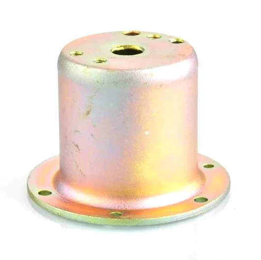
Stiffness without weight: what a drawn shell does best
A deep drawn shell – a closed-end or open cylindrical envelope with thin walls – is the most weight-efficient structural form a press can produce. Its stiffness comes not from thick material but from its curved, closed section: a shell resists bending and torsion through its geometry, much as a tube beats a solid bar of the same weight. That is why drawn shells replace castings and weldments across enclosures, motor housings, covers, and structural guards.
This page is about the engineering of the shell itself – how wall thickness, curvature, and features set stiffness and failure modes, and how to specify a shell that is light without being fragile.
Why a curved shell beats a flat panel
A flat panel resists out-of-plane load only through its thickness, so doubling stiffness requires eight times the thickness (stiffness scales with thickness cubed). A curved or closed shell resists the same load by developing membrane and hoop stresses in its surface, so a much thinner wall achieves the same stiffness:
- A closed-end cylinder is stiff in bending along its axis and very stiff in torsion, which is why a drawn can makes a good structural enclosure.
- A domed end (a spherical or ellipsoidal cap) is dramatically stiffer per unit weight than a flat end, which is why covers carrying pressure or handling loads are domed rather than flat.
- A flange around the open end acts as a stiffening ring, reducing the ovalisation of the open rim under load.
The practical implication: a designer who needs a stiff cover should ask for a dome, not a thicker flat plate. The drawn part does the work with geometry.
Wall thickness: what it controls and what it does not
Wall thickness in a drawn shell sets three things, in this order of importance:
- Local strength at features – a thread, a bearing seat, a weld lip. Here the wall must be thick enough that the local stress does not exceed the material’s capacity; this often sets the minimum sheet size, even though the shell’s global stiffness does not need it.
- Local buckling resistance – a thin shell under compression or handling can dent. Below a certain wall-to-diameter ratio, a shell is easy to deform by hand; the customer almost always wants a shell that survives the plant as well as the load.
- Global stiffness – the least sensitive, because geometry dominates. This is why we push back when a customer thickens the whole shell to fix a stiffness problem that a rib or a dome would solve for less weight.
The failure modes we design against
Three modes govern a thin drawn shell:
- Local buckling / denting under handling or impact – resisted by a minimum wall for the diameter and by generous radii at features.
- Ovalisation of the open end under load – resisted by a flange or a beaded rim, or by a close-fitting mating part that supports the rim.
- Fatigue at a sharp transition – a fillet between the base and the wall, or a step in the wall, is where cracks start under vibration. We keep fillet radii at least 2× the wall, and avoid abrupt section changes.
None of these is fixed by choosing a more expensive material; they are geometric, and they are resolved at the drawing stage. That is the most useful conversation we can have with a designer early in a program.
Features that add stiffness cheaply
Because stiffness is geometric, small die features pay for themselves:
| Beads and ribs | A formed rib along a shell raises its bending stiffness locally for almost no added weight. Often a pair of ribs across a flat area removes a need for thicker metal. |
|---|---|
| Flanged rim | A stiffening ring at the open end; also gives the mating part something to seat against. |
| Domed end | Converts a flat end into a load-carrying surface; the single most effective stiffening change for a cover. |
| Integral boss | A coined boss for a fastener concentrates load in a controlled thickness rather than relying on the shell wall. |
Material: what it changes and what it does not
Material choice affects corrosion, temperature capability, magnetic or thermal behaviour, and cost – but for a given geometry it changes stiffness only through the elastic modulus, and all common steels have essentially the same modulus. Switching from mild steel to stainless steel does not make a shell stiffer; it makes it corrosion-resistant. Aluminium has about a third of steel’s modulus, so an aluminium shell of equal weight is less stiff unless the geometry is redesigned. We make this point often, because “make it stiffer” and “make it stainless steel” are different problems.
Surface, finish and the shell’s service environment
A drawn shell carries drawing lubricant and smeared metal on its surface, so a shell destined for a corrosive environment needs a passivation or a coating step, and one destined for an electrical application needs the surface left conductive. We match the finish to the function and document it, rather than leaving it to a default.
How thin is too thin, and where the floor is
How thin can a shell be? Practically, 0.3 mm is a working floor for a hand-sized part; below that the shell dents in normal handling regardless of design. For demanding loads the limit is set by buckling, and we will calculate it rather than guess.
Can you add ribs without extra tooling cost? A rib is a die feature; it adds a little tooling cost but often lets us use thinner, cheaper material, so the net can be zero or negative.
Will a domed end hold pressure? A dome is the best shape for pressure; how much it holds depends on the dome radius, the wall, and the material, and we will run that calculation for the customer’s pressure.
What if the shell must be both stiff and thin for weight? Then the design has to use geometry – dome, ribs, a flanged rim – and we will propose those features rather than simply thickening the wall.
Specifying a deep drawn shell
Give us the envelope dimensions, the loads (handling, pressure, vibration), the mating interfaces at the open end and the base, the environment for material selection, and any electrical or magnetic requirement. With those we can choose the wall for the loads that actually matter, add the geometric features that deliver stiffness without weight, and quote a shell that is as light as it should be and as strong as it needs to be – which is the point of deep drawing in the first place.
Choosing between drawing, machining and welding comes down to the shape of the part: the guide to deep drawn covers sets out where each route wins, and the overview page links through to the full Precision Deep Drawn Parts range.
Specifications
| Item | Deep drawn shell |
|---|---|
| Brand | AUNOV |
| Designing | Quotation follows the print, not a catalogue – samples are reverse-measured into a controlled drawing; the approved drawing is kept as the controlled master. |
| Tooling | Dies, fixtures and gauges are made in our own toolroom, so die cost stays transparent, and first-article timing is measured from the tooling start date. |
| Samples | Sample approval is documented: dimensions, finish and material recorded for later comparison. |
| Materials | Carbon steel (SPCC / DC01), 304 / 316 stainless steel, aluminium and brass are held on site; material substitutes are proposed only with your written approval. |
| Surface finish | Plating, powder coating, anodising or polishing, per the print; alternatives quoted with the quotation, samples approved in writing. |
| Processing | Multi-stage deep drawing with interstage annealing, trimmed and pierced in following dies; every stage is logged against your part number. |
| Equipment | Mechanical presses 5-250 T plus 250-500 T hydraulics, with in-line annealing, with CNC turning centres for secondary operations and CMM inspection. |
| Tolerance | +/-0.05 mm on drawn diameters, tighter bands confirmed against the drawing; critical dimensions carry CMM data with the shipment. |
| Delivery terms | CIF or DDP, with FOB available, payment by T/T or L/C, quoted in USD or EUR; sea or air freight is quoted to your door. |
Frequently Asked Questions
Is a shell different from a cup or a can, or is it only naming?
The naming follows what the part has to do, and it changes what gets written on the drawing. A cup is judged by how much depth it holds and whether it survives the draw needed to get there. A can usually has a defined end that has to contain something, so its pressure boundary is the point. A shell generally wraps or encloses something else, so fit, stiffness and how the open end interfaces matter more than containment. Treating all three as one family is how drawings end up specifying the wrong controlling dimension first.
What are the cheap ways to add stiffness to a thin shell?
Geometry rather than material. Beads, ribs, steps and a rolled or hemmed edge all raise stiffness for almost no added weight, which is precisely the reason for choosing a drawn shell over a flat panel plus brackets. Orientation matters: a bead running around the circumference resists ovaling and denting loads, while features running along the draw direction have to survive the drawing itself, so their depth and radius are limited by forming instead of chosen freely. Settling this at quotation stage means the stiffening is designed into the tool rather than added afterwards.
Where does the practical wall floor come from, if not from the press?
From everything that happens after forming. The drawing operation will produce walls thinner than a hand-sized part can survive being handled, welded, threaded or plated, and in this size range around 0.3 mm is the working floor before the part starts suffering in transport and assembly rather than in the die. Corrosion allowance argues for leaving a little material, and finishing argues for it again. The floor is therefore an application answer rather than a capability answer.
Does a shell have to be finished all over?
No, and saying so on the drawing is usually money saved. Most shells have one face anyone sees and the rest hidden inside an assembly, so specifying cosmetic requirements only where they count avoids paying to polish surfaces nobody looks at. Masking for plating or coating follows the same logic. Where a shell genuinely has two visible faces, that also belongs on the print, because it changes how parts can be racked and handled through finishing.
Related Products


Request a Quote for This Part
Send a drawing or sketch — get material advice, tooling cost and a per-piece price within 24 hours (working days).