
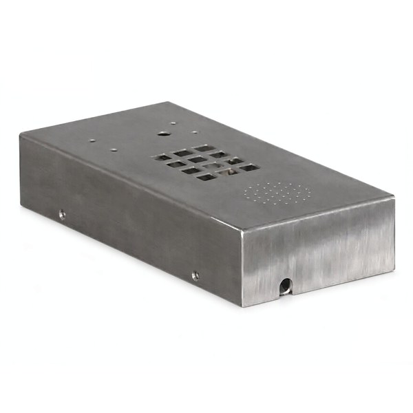
A louver is not a hole with a roof over it
A pierced hole removes material. A louver moves it. That difference decides everything else about a vented cover, because the louver is formed by stretching a bridge of sheet across a die opening and leaving the displaced metal attached on three sides. The open area you get is therefore not simply the area of the punch; it depends on how far the metal is lifted and how much it thins on the way up. Two covers with identical tooling drawings can have substantially different airflow if one press is set 0.3 mm deeper than the other.
This is why a vented cover has to be specified by the airflow it must pass, not by the number of slots. A drawing that says twenty louvers of 30 by 5 mm describes a punch, not a product. The product is a defined free area with a defined direction, and both of those have to be written down if the cover is going to be compared against another supplier later.
Free area is the number, and it is not the same as open area
Free area is the measured area through which air can actually pass, projected normal to the flow. Because a louver stands off from the panel and has a bridge at one end and two side webs, the free area is always smaller than the nominal opening, and the shortfall is larger than most people expect. As a rule of thumb for conventional louvers formed in 1.0 to 1.5 mm steel, expect to achieve between 40 and 60 percent of the nominal opening as true free area. A cover designed against the nominal figure will be undersized and the equipment will run hot.
The second reduction is the discharge coefficient. Even the free area is not fully effective because air entering at an angle meets the louver edge and separates. A practical vented cover with slotted louvers typically behaves as though its free area were 70 to 85 percent effective when the airflow is calculated with a simple orifice equation. Designers who skip this factor usually discover it in a thermal test, after the housing has been tooled.
- State the required free area in square millimetres, or the required flow at a stated pressure drop.
- State the direction the air is expected to travel through the cover, because a louver is directional.
- Give the pressure drop you are designing against. A free area figure without a pressure is only half a specification.
- Decide whether the airflow is forced or buoyancy driven. A buoyancy driven cover tolerates much more restriction than a fan driven one.
The bridge is the smallest part of the louver and it carries the most
The bridge is the strip of metal left at the closed end of each louver. It is the only thing joining the louver to the panel, and it is where the forming strain is highest. Bridges crack at the corner between the bridge and the side web, usually on the third or fourth tool sharpening rather than at first article. Two numbers control this: the bridge width relative to material thickness, and the inside radius at the transition.
A bridge width below two times the material thickness will not survive production on carbon steel, and on 304 or on an aluminium sheet with limited elongation it will not survive the first article. Bringing the bridge to three to four times the thickness costs a little free area and removes almost all of the cracking risk. The transition radius between the bridge and the side web should be at least one material thickness; a sharp internal corner there concentrates the strain and becomes the crack initiation site.
Thinning is worth measuring rather than assuming. On a 1.2 mm steel cover with a 4 mm lift, the metal at the leading edge of the louver can be expected to measure 0.95 to 1.05 mm after forming, and the bridge can measure 0.90 mm. If the drawing calls out a minimum wall anywhere near the louver, that minimum has to be checked at the bridge, because it is consistently the thinnest point on the part and it is the point that a general wall thickness note will miss.
Orientation decides whether the cover sheds water or drinks it
A louver has a facing direction. Facing down, it sheds water and blocks a direct line of sight. Facing up, it collects water on the inside face of the louver, and that water then runs backwards into the housing along the underside of the bridge. On an outdoor enclosure the difference between the two orientations is the difference between an IP54 cover and a cover that fills with condensate. The direction has to be stated relative to the mounting position of the finished equipment, not relative to the flat blank, because the same cover is inverted the moment it is fitted the other way round.
Dust behaves in the opposite way to water. A downward facing louver is good against rain and worse against fine dust, because the pocket behind the louver traps particles that a simple hole would let fall through. Where both matter, the usual answer is a downward facing louver over a secondary mesh or a foam filter, and the filter becomes a service item that the drawing should identify. If a filter is fitted, say so, because the free area calculation changes entirely once a filter is in the path and the filter will need to be replaced on a schedule that nobody will remember unless the maintenance drawing shows it.
Louvres cut into a drawn shell: sequence and distortion
Forming louvers into a cover that is already drawn is a different problem from forming them into a flat panel. The louver tool needs a flat surface to sit against, and the bottom of a drawn cover is flat only in the middle. Where louvers run close to the corner radius, the tool cannot support the metal properly and the louver will be shallower at one end than the other. The usual fix is to place louvers no closer than one wall height plus one material thickness from the corner transition, or to form them on a shallow platform coined into the bottom of the cover first.
Sequence matters as well. Punching the slots before drawing distorts them: the slots move and stretch with the shell, and their positions end up with some fraction of the draw variation folded in. Forming the louvers after the last draw keeps them dimensionally honest, at the cost of one more station and the risk of distorting the drawn shell. In practice the louvers are formed after the draw, the shell is then restruck to bring back flatness, and the flatness is checked after the louver station because that is where it is lost.
- Louvres after the last draw, restrike after the louvers.
- Keep louvers one wall height clear of the corner radius.
- Locate the louver tool on the inner wall of the cover, not on the trimmed flange.
- Measure flatness downstream of the louver station, not before it.
How we verify a vented cover before it ships
A vented cover is judged on two independent things – that it vents what it should, and that cutting the louvers did not quietly weaken or distort the shell it sits in. We verify both, because a cover that passes a visual vent check but has gone out of flat around the opening will not seal, and a cover that is perfectly flat but under-vented will overheat the unit behind it.
- Measure free area against the quoted number with a template or by sectioning one louver; accept only within the stated tolerance, not the open-area guess.
- CMM the panel flatness and the louver-row straightness after forming; flag any panel that moved more than the flatness callout during piercing.
- Check the bridge width on a sample louver; a bridge below minimum is a fatigue risk and rejects the pierce punch setting.
- Confirm louver direction and tilt with a go fixture so the cover sheds water the way the drawing intends, not the reverse.
- Burr and edge check on the louvers; sharp or torn bridges snag assembly gloves and indicate a dull punch.
- File the vent-area calculation, the flatness report and the first-article section under the part number.
If you are comparing this part with a machined or welded alternative, the guide to deep drawn covers lays out where drawing wins, where it loses, and what it costs either way.
Specifications
| Item | Steel Deep Drawn Vented Cover with Louver Slots |
|---|---|
| Brand | AUNOV |
| Designing | Send us your 2D drawing, or mail a sample for measurement, the quotation comes back with a manufacturability review attached. |
| Tooling | Every die designed and built in our toolroom, stored under your part number. |
| Samples | First articles go out with dimensional data plus material certs. |
| Materials | Carbon steel (SPCC / DC01) leads the stock list for this part, alongside 304 / 316 stainless steel, aluminium, brass and copper, and the grade is fixed at the drawing review. |
| Surface finish | Your print chooses between plating, e-coat, powder coating, anodising or passivation. |
| Processing | Staged deep drawing with in-line annealing where needed, pierced and finish-machined on the same floor. |
| Equipment | Our press floor runs 5-250 T mechanical and 250-500 T hydraulic presses, CNC turning centres and a climate-controlled CMM room. |
| Tolerance | As-drawn tolerance +/-0.1 mm, machined features held to +/-0.03 mm. |
| Delivery terms | FOB as standard, DDP available for EU and US destinations, payment T/T or L/C, D/P for repeat accounts, call-off scheduling supported. |
Frequently Asked Questions
How is a louver different from a punched hole?
A pierced hole removes material; a louver moves it. The louver is formed by stretching a bridge of sheet across a die opening and leaving the displaced metal attached on three sides, so the opening you get is a consequence of how far the metal was lifted and how much it thinned on the way up.
Why specify a vented cover by airflow rather than by the number of slots?
A drawing that counts slots describes a punch, not a product. Free area depends on forming depth, so two covers off identical tooling drawings can pass substantially different airflow if one press is set a fraction of a millimetre deeper, and only a defined free area with a defined direction survives comparison against another supplier later.
What is the bridge, and why does it carry the most?
The bridge is the displaced panel itself, and it is the smallest element in the feature. Once it is lifted it becomes the structural connection between louver and sheet, carrying both handling loads and whatever the cover sees in service, which is why it gets more attention than either slot dimension.
Does louver orientation really change performance?
Yes, decisively. Orientation decides whether the cover sheds water or drinks it, and it also decides which direction air is allowed to move, so orientation belongs on the drawing as a controlled feature rather than as a detail left to the press setting.
Related Products


Request a Quote for This Part
Send a drawing or sketch — get material advice, tooling cost and a per-piece price within 24 hours (working days).