
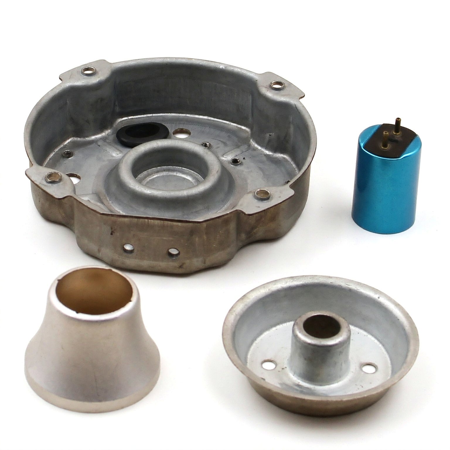
A wick tube is a concentric inner feature, and concentricity is the whole job
A canister shell with a wick tube is a shell within a shell, and the entire value of the part is the concentricity of the inner tube to the outer shell. The wick tube is the passage the wick or the wick carrier runs through, and if it is off-axis to the shell, the wick rubs, the seal at the tube fails, and the canister leaks or jams. Customers sometimes specify the tube diameter and the shell diameter and forget that the number that matters is the offset between them, so we put concentricity at the top of the specification and treat the two diameters as secondary.
We express the requirement as a concentricity or runout tolerance from the shell axis to the tube axis, typically 0.1 to 0.2 mm total depending on the wick clearance, and we verify it directly rather than inferring it from two diameter readings taken on different centers. A shell and a tube can both be in diameter tolerance and still be 0.3 mm off-axis, which is the failure, and only a concentricity check catches it. The tube is therefore the datum-linked feature, not an independent hole.
The concentricity is won at the draw, not at inspection. If the tube is formed from the same blank as the shell in one operation, it stays concentric by construction; if it is pierced or redrawn separately, every stage is a chance to introduce offset, which is why we prefer to form the tube in the same hit as the shell wherever the geometry allows.
Drawing the shell and the tube in one hit or redrawing the tube
There are two ways to make the wick tube. The cleaner way is to draw the shell and the tube together from a single blank with a punch-and-mandrel arrangement that forms the outer shell and the inner tube in one stroke, so the two are concentric by the tooling, not by adjustment. This works for tubes that are not too deep relative to the shell, and it is what we specify wherever the drawing permits, because it removes the offset risk entirely.
Where the tube is deeper than a single hit allows, we draw the shell first, then redraw the tube in a second operation on a mandrel, locating the redraw from the shell OD so the tube is centered on the shell it was drawn from. The redraw is the step that can introduce eccentricity if the locator is off, so we hold the locate tight and check the concentricity on the first article before committing the tooling. A tube redrawn off a sloppy locator is a tube that runs to one side, and the only fix is a better locator, not a bigger press.
The blank for the combined draw has to feed both the shell wall and the tube wall, so it is larger than a plain shell blank, and the draw ratio on the tube is the limiting one. We calculate the tube draw ratio separately and stage it where it exceeds the LDR, with annealing between stages because the tube wall work-hardens just as the shell does.
The tube bore carries a wick, so ID finish matters more than OD
The wick tube’s outer diameter is mostly there to keep it concentric and to give the draw something to form; the surface that matters is the bore, because the wick or its carrier slides through it. A bore that is rough or has draw marks catches the wick and sheds fibres, and a bore that is out of round jams the carrier. We hold the tube ID finish to a drawn standard and machine it where the wick clearance is tight, referencing the bore to the shell axis so the machined tube stays concentric to the shell.
The ID is the datum for any feature on the tube, not the OD, for the same reason a sleeve’s bore leads: the tube is a passage, and a passage is defined by its inside. We machine the tube ID on a turning center located from the shell OD, so the cut bore is centered on the shell even if the as-drawn tube was slightly off, and we verify the ID after machining, because the wick meets the machined surface, not the drawn one.
Where the wick is fragile, we specify the ID finish explicitly, because a smooth drawn bore may be enough and saves the machining cost, but only a measured finish confirms it. We record the ID roughness on the first article so the wick supplier has a real number.
- Hold the tube ID as the datum; the OD is secondary to concentricity.
- Machine the bore referenced to the shell axis so it stays centered.
- Specify and measure the ID finish where the wick clearance is tight.
- Draw the shell and tube together where geometry allows, to remove offset risk.
Eccentricity between shell and tube shows up as a sealing leak, not a dimension
The failure of a wick tube is rarely a dimension out of tolerance on a report; it is a leak or a rub in service that traces back to eccentricity. If the tube is off-axis, the annular space between tube and shell is wider on one side, and a seal that is sized for the average gap leaks on the wide side and over-compresses on the narrow side. The report said both diameters were fine; the field said it leaked, because the report never measured the offset.
We close that gap by measuring concentricity directly on the first article with a co-ordinate check or a runout gauge referenced to the shell OD, and by auditing it on production, because a drift in the redraw locator shows up first as a growing eccentricity, then as a leak, and the eccentricity check catches it a step earlier. The acceptance criterion is the offset, stated as a total runout, not two diameters compared after the fact.
For canisters that are pressurized or that hold a fluid around the tube, the eccentricity also sets the wall thickness on the narrow side, and a thin narrow side is a thin pressure boundary, so the concentricity check doubles as a wall check on the tight side.
Wall between tube and shell is the thin bridge that limits the draw depth
The material between the wick tube and the outer shell is the bridge that both tubes share, and it is the thin spot that limits how deep the canister can be drawn. As the shell and tube are drawn together, that bridge wall is stretched around two radii at once, the outer shell corner and the inner tube corner, and it thins more than either wall alone. Below a certain bridge thickness the draw either tears at the bridge or the tube collapses into the shell, and that thickness is the real limit on depth, not the shell diameter.
We calculate the bridge wall from the blank and the two draw ratios, and we section the first article through the bridge to confirm the minimum, because the bridge is the one place a calliper cannot reach and the thin spot lives. Where the depth demands more than the bridge can give, we thicken the blank locally at the bridge, add an anneal, or split the tube draw into an extra stage, because you cannot recover a torn bridge by pressing harder.
The bridge also has to stay concentric, because if it thins unevenly around the circumference the tube drifts toward the thin side, which closes the loop back to the concentricity requirement. The bridge wall and the eccentricity are the same feature seen as thickness and as position, and we check both on the same section.
How we verify a concentric tube that a standard bore gauge cannot reach
A wick tube is verified for concentricity as much as for size, because a standard bore gauge reads the tube ID but not its offset from the shell. The first article carries the checks below and production is audited against it.
- Concentricity or total runout from the shell axis to the tube axis is measured directly, not inferred from two diameters.
- Tube ID is gauged and its finish recorded where the wick clearance is tight, referenced to the shell axis.
- Bridge wall thickness is sectioned on the first article and the minimum recorded as a controlled characteristic.
- Shell and tube diameters are checked to their own regimes, drawn and machined as specified.
- Eccentricity is audited on production so a drifting redraw locator is caught before a leak.
- Material and heat are traced to the mill certificate so the shipment documents the steel drawn.
Send the drawing or a sample canister, and the review returns the concentricity we will hold, the tube ID finish, and the bridge wall we will section, so the canister that ships carries its wick true.
The engineering calls behind a part like this — draw ratio, wall thinning, radii and trim — each get worked examples in our deep drawn covers guide; the Precision Deep Drawn Parts pages gather the rest of the family.
Specifications
| Item | Steel Deep Drawn Canister Shell with Wick Tube |
|---|---|
| Brand | AUNOV |
| Designing | Send the drawing, or a sample we can measure, you get a DFM review together with the quotation. |
| Tooling | Every die designed and built in our toolroom, held and maintained under your part number. |
| Samples | Pre-production samples ship with a full dimensional report and material certification. |
| Materials | Stock for this part leads with carbon steel (SPCC / DC01), alongside 304 / 316 stainless steel, aluminium, brass and copper, with grade selection confirmed at drawing review. |
| Surface finish | Surface treatment per the drawing: plating, e-coat, powder coating, anodising, passivation, per your print. |
| Processing | Multi-stage drawing, annealed in line where wall thinning calls for it, then pierced and machined in house. |
| Equipment | Press capacity from 5 to 500 T across mechanical and hydraulic lines, CNC cells plus a temperature-controlled CMM room. |
| Tolerance | +/-0.1 mm on as-drawn features, +/-0.03 mm on machined surfaces. |
| Delivery terms | FOB standard, DDP offered for EU and US, T/T and L/C accepted, D/P for established customers, call-off scheduling supported. |
Frequently Asked Questions
Which dimension actually matters on a canister with a wick tube?
The offset between the two, not either diameter. A shell and a tube can both sit inside their own diameter tolerances and still be 0.3 mm off-axis, which is the failure: the wick rubs, the seal at the tube lets go, and the canister leaks or jams.
How is that requirement written and checked?
As a concentricity or runout tolerance from the shell axis to the tube axis, typically 0.1 to 0.2 mm total depending on the clearance the wick needs. It is verified directly rather than inferred from two diameter readings taken on different centres, so the tube is treated as a datum-linked feature and not an independent hole.
Is the tube drawn together with the shell or afterwards?
Drawing both in one hit gives the best inherent alignment, but where the depth demands more reduction than the thin bridge can take, the tube is redrawn in a separate stage. The choice is made from how deep the tube has to go and how tight the concentricity is.
Why does the tube bore finish matter more than its outside diameter?
Because the wick runs through the inside. Anything that raises friction or catches the wick in the bore shows up immediately as poor feed or a jam, while the outside surface mostly has to exist at the right place.
Related Products


Request a Quote for This Part
Send a drawing or sketch — get material advice, tooling cost and a per-piece price within 24 hours (working days).