
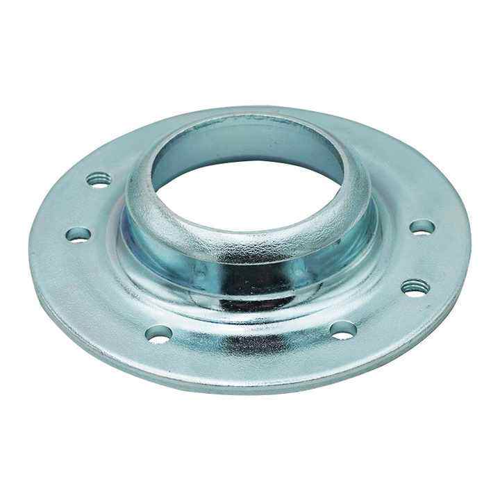
The center boss is a locating feature: concentricity is the whole part
A flange with a center boss is, functionally, a locating ring: the flange bolts the part down, and the boss piloting into the mating assembly is what actually positions it. Gears, pulleys, fans, bearing housings and motor-mounted components all use this geometry – the bolt circle provides clamp, the boss provides location, and the two duties are different. That makes the boss a concentricity problem above everything else. A boss off-center by 0.2 mm moves a mounted rotor 0.2 mm off the machine axis, which shows up as runout, imbalance, seal wear and noise – none of which bolt torque can fix, because the bolts clamp and the boss locates.
Concentricity must be designed into the process route, because it cannot be inspected in afterwards. The drawn route has the same drift risk as any flange ring: the boss forms with the draw, the flange OD is trimmed later, and if the trim locates off the wall rather than off the boss, the wall-to-flange eccentricity lands on the finished part on top of the boss-to-wall eccentricity. When the drawing calls a concentricity tighter than the as-drawn chain can hold – typically 0.1 to 0.15 mm through draw plus trim – we route the part through machining: flange OD and boss (or boss bore) turned in one CNC setup, located from the boss itself, collapsing the tolerance chain into a single clamping. Machined this way, boss-to-flange concentricity of the 0.03 mm class is routine, and that is the number most locating duties actually need.
Drawing a boss: metal gain at the center versus thinning at the flange
A center boss on a drawn flange is an embossed dome – the punch pushes the blank center up while the flange region holds or flows – and the metal accounting has to balance. Forming a boss stretches the center: the crown thins 5 to 15 percent relative to the blank depending on boss height and diameter, exactly like a shallow dome. The metal feeding the boss comes partly from the surrounding flat, which draws inward if the binder lets it, and the competition between center stretch and flange inflow decides where the thinning lands.
The flange side of the ledger has its own problem: the boss forming force pushes outward on the material around it, and on a thin flange that pressure can wrinkle the flat between boss and edge – rejects on any sealing or bolting flange. The controls are conventional draw controls applied to an emboss: binder pressure over the flat zone, a draw bead or stepped binder where the flange flows too freely, and a punch nose radius on the boss generous enough to spread the stretch – we form bosses with nose radii of at least 3 to 4 times thickness unless the drawing forces a sharper profile, and a sharper profile gets a staged form and a thinning check rather than a hopeful single hit.
Machining the boss bore: when plus or minus 0.03 mm is worth paying for
Many boss flanges carry their function in a bore through the boss – a bearing seat, a shaft clearance, a seal land, a pressed bushing housing – and bores are where the as-drawn and machined worlds part ways. A drawn or pierced boss bore holds around ±0.1 mm: fine for clearance around a free shaft, inadequate for a bearing OD or a seal, both of which want the 0.03 mm class or better, plus roundness and finish that only cutting delivers. The decision rule we apply at quotation:
- Free shaft, generous clearance: pierced or drawn bore, ±0.1 mm, no machining. The cheap, fast, correct answer.
- Bearing seat, bushing housing, seal land: machined bore. We drill and bore, or turn the bore, in the same setup as the flange face and OD wherever possible – one clamping gives bore-to-flange concentricity, bore-to-face squareness and finish together, instead of stacking a second clamping’s location error on top.
- A sized bore as the middle path: where a pierced bore is close but not enough, a sizing ball or taper punch pushed through irons it to size and roundness in one fast stroke, no chips, at a fraction of turning cost. Sizing also burnishes the bore surface, a genuine benefit for a running fit.
Zinc coverage in the boss-to-flange transition zone
Zinc plating a boss flange has one predictable soft spot: the fillet where the boss root meets the flange face. Electroplated zinc follows current density, and a concave fillet between two raised features is an electrical low-land – the deposit there runs measurably thinner than on the boss flank or the flange flat. The fillet is also, mechanically, the most stressed zone on the part – the boss’s bending load resolves into the flange through that fillet – so the thinnest zinc sits on the most stressed metal – the recipe for fillet rust and stress-corrosion, invisible to a thickness gauge reading taken on the easy surfaces. We manage the transition zone deliberately:
- A generous root radius in the die – at least 2 to 3 times material thickness – both reduces the plating shadow (a shallower concave plates better than a tight one) and lowers the stress concentration that makes the zone corrosion-sensitive in the first place. One radius fixes two problems.
- Thickness spot-checks in the fillet at first article, by angled gauge or XRF per ISO 3497 on a sectioned or sacrificial part; the acceptance floor for the fillet is set as a percentage of nominal – typically 60 to 70 percent – and written into the plating spec for the part number.
- Bath and fixture choices: alkaline zinc for better throwing into the concavity, and racking that presents the fillet toward the anode; on deep or tight fillets an auxiliary anode rides with the rack.
- Where the corrosion duty is severe and the fillet genuinely tight, the honest alternative is mechanical zinc or a dip process that does not depend on current distribution; we recommend it rather than fight physics with a marginal electrolytic deposit.
The bolt circle, the boss and the mating part as one dimensional loop
The boss flange assembles as a three-feature system: boss locates, bolt circle clamps, flange face seats. Each feature has its own tolerance, and the mating assembly carries the other half of each interface – so tolerances must be allocated with the mating part in view, not in isolation. The classic failure is a bolt circle positioned from the boss with a tight tolerance while the mating part’s holes are positioned from its pilot bore with a different tolerance: the two position systems fight, and on a fixed-fastener joint the effective tolerance is the sum of both patterns’ position errors plus half the clearance. We run the loop arithmetic in the review, and our contributions to closing it:
- Bolt holes pierced after drawing, located from the boss – the same datum the assembly uses – so the pattern’s position tolerance is not stacked under the draw’s geometry drift.
- Hole size with plating allowance where the part is zinc plated: zinc adds to the hole’s surface, so production piercing opens the hole by the deposit’s double thickness, and the assembled fit is the drawing’s fit, not the unplated one.
- Concentricity allocation: if the boss pilots with a close fit and the bolt holes are clearance, we put the accuracy money in the boss and let the bolt holes breathe – also the cheaper allocation, since a machined boss in one setup costs less than a machined bolt pattern.
- Flange face squareness to the boss on parts that clamp a bearing or seal: the face is machined with the boss bore in one setup, so face squareness and bore concentricity come from the same clamping and the loop has one link, not three.
How we verify boss concentricity and flange squareness
Each boss-flange part number carries a measurement plan matched to its route:
- Boss concentricity to the flange OD – two-probe runout on a rotating table or CMM relationship measurement. As-drawn route: 0.1 mm class; machined route: 0.03 mm class, measured after the final cutting pass.
- Boss diameter and roundness – or bore diameter, roundness and finish where the boss is bored – at first article on every piece, in production on the sampling plan; a sized bore is checked after sizing, not before.
- Flange face squareness to the boss axis and flange flatness, gauged in the same setup as the concentricity wherever the route allows, so the measurement chain matches the machining chain.
- Boss height and root fillet condition: height from the flange face to datum, plus a visual and sectioned check of the root radius at first article – no wrinkles, no cracks, radius within the drawing minimum.
- Wall thickness at the material-accounting stations – crown, root, flat, flange edge – by ultrasonic or section on the first article, against the drawing’s minimum band.
- Bolt pattern by CMM at first article and a go-pin composite gauge in production, hole size checked after any plating allowance adjustment; fit confirmed with the mating part or gauge on the sampling plan where the joint is fixed-fastener.
- Plating verification: deposit thickness on flange flat, boss flank and – specifically – the root fillet, against the part number’s fillet floor, plus adhesion and salt-spray evidence per the plating plan.
- Records: first-article dimensional report, machining setup sheet, plating certificates and the tooling archive under your part number, so the reorder reproduces the concentricity, not just the shape.
Not sure whether to draw, machine or weld this geometry? The guide to deep drawn covers compares the three routes and shows where each one wins; the full Precision Deep Drawn Parts range is linked from the overview page.
Specifications
| Item | Zinc Plated Deep Drawn Flange with Center Boss |
|---|---|
| Brand | AUNOV |
| Designing | Send drawings, or send a sample to be measured, you get a DFM review together with the quotation. |
| Tooling | Dies designed and built in our own toolroom, held and maintained under your part number. |
| Samples | Samples for approval come with a dimensional report and material certificate. |
| Materials | Carbon steel (SPCC / DC01), 304 / 316 stainless steel, aluminium, brass and copper, and the grade is fixed at the drawing review. |
| Surface finish | Zinc, nickel or chrome plating, e-coat, powder coat, anodising or passivation, per your print. |
| Processing | Staged deep drawing with in-line annealing where needed, with piercing and finish machining under the same roof. |
| Equipment | Mechanical presses 5-250 T, hydraulic presses 250-500 T, in-house CNC cells and a temperature-controlled inspection room. |
| Tolerance | +/-0.1 mm on as-drawn features, +/-0.03 mm after machining. |
| Delivery terms | Prices FOB, with DDP for EU and US on request, T/T and L/C; D/P on repeat accounts, call-off scheduling supported. |
Frequently Asked Questions
Why is the center boss the whole part on a locating flange?
The flange bolts the part down, but the boss pilots into the mating assembly and actually positions it; gears, pulleys, fans and bearing housings all use this. A boss off-center by 0.2 mm moves a mounted rotor 0.2 mm off axis, showing up as runout, imbalance and noise that bolt torque cannot fix.
How is boss concentricity designed into the process?
When the drawing calls for tighter than about 0.1 to 0.15 mm, the part is routed through machining: flange OD and boss turned in one CNC setup, located from the boss itself, collapsing the tolerance chain into a single clamping.
What happens to zinc coverage at the boss-to-flange transition?
The transition zone is where the coating can thin or bridge, so zinc coverage there is checked because it is the spot most exposed after forming. Plating thickness and adhesion are verified on the first article.
How is boss concentricity verified?
Boss-to-flange concentricity and flange squareness are measured, routinely to the 0.03 mm class when machined. The typical minimum order is 1,000 pieces with a 24-hour quotation.
Related Products


Request a Quote for This Part
Send a drawing or sketch — get material advice, tooling cost and a per-piece price within 24 hours (working days).