
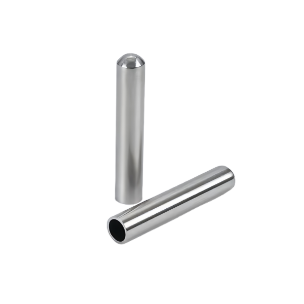
Closing an end by drawing: the dome is a formed feature with its own rules
A drawn tube with one rounded closed end is a different kind of product from an open tube, because the closed end is not a cap added afterward – it is the tube’s own material pushed into a dome by the drawing process, and its properties follow forming physics rather than machining physics. The dome is thicker or thinner than the wall depending on how it was made, its shape is set by the punch profile, and its integrity is a function of the draw schedule. Getting the closed end right means treating it as the part’s primary formed feature, which is how we build the process and how the drawing should specify it.
There are two ways to close a tube end by drawing, and they produce different domes:
- Nosing the open end inward: the tube’s lip is pushed inward and closed, and the dome is made from the tube’s own wall. The dome thickness follows the wall and the shape converges toward a rounded nose. This is the natural closing method for shallow domes and moderate wall tubes, and it leaves a small residual aperture or a fully closed nose depending on depth.
- Deep drawing a cup and ironing it into a tube: the part begins as a drawn cup – the closed end is the cup’s original bottom, and the tube body is ironed down from the cup wall. This produces the strongest closed end (the dome is the parent sheet’s least-deformed zone), precise dome thickness control, and a wall that can be ironed to a specified thickness along the length. It is the method for pressure-bearing and thin-wall closed-end tubes, and it is our default for anything with a stated burst or pressure figure.
Wall distribution in the dome, and why the pole is the thin place
Wall distribution in a drawn closed end follows the strain path of the material, and knowing the pattern is the difference between a drawing that specifies the dome successfully and one that scrapes through inspection. On a cup-drawn closed end, the original flat blank’s bottom centre barely deforms at all – it just moves down with the punch – while the material near the bottom corner bends, unbends and stretches. The wall distribution from pole to wall junction is therefore:
- At the pole: close to original stock thickness on a shallow dome; progressively thinner as the dome gets deeper relative to its diameter, because a deep dome’s pole material genuinely stretches biaxially to wrap the punch nose. On deep domes – depth beyond half the diameter – pole thinning of 8-15 percent is normal and predictable.
- At the transition radius (dome-to-cylinder): the thin band, always. Bending and unbending around the punch and die radii plus circumferential stretch put this zone 10-20 percent below stock with standard radii. We control it with punch radius selection and, where the dome is pressure-bearing, with a local thickening of the blank – a coined preform that gives the transition zone extra material to spend.
What a rounded closed end can hold: burst and collapse in one shape
The rounded closed end is, mechanically, a pressure structure – and a good one. A dome under internal pressure carries the load as membrane tension spread across a double curvature, which is why closed-end tubes hold several times the pressure of an open tube capped by a flat disc of the same wall. But the dome also carries two failure modes the open tube does not, and both are worth specifying against.
The two modes:
- Burst at the transition band. Internal pressure generates the highest combined stress where the dome’s curvature meets the cylinder’s – hoop stress plus the dome’s membrane tension plus the bending introduced by the shape change. The thin band described above and the stress peak coincide by geometry, which is why burst failures on drawn closed ends almost always start a few millimetres off the dome’s shoulder, not at the pole and not mid-wall. Burst is tested hydrostatically behind a barrier on sample parts, at the stated multiple of service pressure per the drawing or the application standard.
- Collapse under external pressure. A closed-end tube that lives in a pressurized environment – a submersion probe, a downhole tool, a vacuum application – fails by the wall buckling inward, and buckling is not a strength calculation but a stability one: it depends on diameter, wall, length and ovality, and a dome that is 5 percent oval collapses at a meaningfully lower pressure than a round one. We verify roundness on the body by gauging, and for collapse-critical parts we state an ovality limit and verify it at three stations along the body.
The drawing-level decisions that make the closed end robust:
- State the duty as a number. “Pressure resistant” is not a specification; “proof to 4 MPa, burst not less than 8 MPa, leak-free at 3 MPa” is. The numbers route directly into the process: dome route selection, wall schedule, preform coin, and the test plan.
- Let the dome be a dome. A drawn dome is strongest when its depth-to-diameter ratio sits in the classic range – roughly 0.3 to 0.5 of the diameter. Specifying a very shallow dome gains package length and loses the membrane advantage; specifying a very deep dome costs pole wall. Where the envelope permits, staying in the strong range is free burst margin.
- Agree the test, not just the number. Hydrostatic burst on samples, pneumatic or immersion leak test at proof pressure on 100 percent of pressure-critical parts, hold time stated – the test plan is part of the product and it is written into the quotation.
Seal or stop: two different jobs for the same rounded end
Half the closed-end tubes we make are closed for containment – the dome seals fluid in or keeps contamination out. The other half are closed for geometry – the rounded end is a stop, a rider, a guide nose, a float chamber end. The two jobs share a shape and differ in almost every specification, and the drawing conversation goes differently for each.
Containment duty – the dome is a pressure and permeation barrier, and the specification set is:
- Leak integrity as a number – helium leak rate, pressure decay rate, or bubble-test pass criterion, chosen by the application’s sensitivity. Instrument sleeves and sensor housings typically specify helium rates in the 10^-6 to 10^-8 mbar.l/s range or a pressure-decay equivalent.
- Wall minimums at the thin band and pole, verified as described above.
- Surface finish inside the dome where the dome holds fluid that must drain clean – a bright annealed or polished interior with a stated roughness, because the dome is the least swabbable cavity in the product.
Geometric duty – the dome is a working surface, and the specification set shifts entirely to shape and finish:
- Profile accuracy: the dome’s radius and its tangency to the body, verified by profile gauge, optical comparison or CMM. A float’s buoyancy axis depends on the dome’s symmetry; a guide nose’s insertion force depends on its profile; a rider’s rolling behaviour depends on both.
- Concentricity of dome to body: the dome’s apex must sit on the tube’s axis within a stated runout – for a float, an off-axis apex is a permanent tilt in the water.
- Exterior finish: for appearance or rolling surfaces, the dome is polished or bright-annealed to a stated Ra; for weld-seated domes, the finish is left as-drawn or machined where the drawing says so.
Polishing a dome for a float or a probe
The exterior finish of a rounded closed end is its own small engineering problem, because a dome is curved in two directions at once and every finishing method leaves a signature on it. What works on a straight tube wall mutes or exaggerates on a dome, and the polishing plan has to be chosen for the shape.
The methods and their dome behaviour:
- Bright annealing – the dome and body come out uniformly bright with no mechanical contact at all, and the finish follows the as-drawn surface quality. The right default for most stainless steel closed-end tubes: no thickness change, no residual polish media, and an Ra around 0.3-0.6 depending on the prior draw quality. It is also the only finish that treats the bore interior identically to the exterior.
- Mass finishing (vibratory or centrifugal barrel) produces an isotropic finish that wraps the dome evenly, and it is the economical route to a uniform matte-bright dome at production volumes. The caveats are two: media lodging in the open bore (closed one end, open the other – we cap the bore during mass finishing), and edge rounding – the open end’s chamfers and the body’s edges soften measurably, so dimensioned features at the open end are finished after mass finishing, not before.
- Electropolishing brightens, passivates and deburrs simultaneously and is the best finish for domes in corrosive, cleanable or instrument service. It removes 10-25 micrometres of surface, which brightens edges and slightly opens dimensions – on a dome the removal is fairly uniform, at the open bore edge it is where the tolerance check goes. We sequence electropolish before final gauging of plated or masked features, and we agree the removal allowance in the process sheet so the post-polish dimensions are the drawing’s dimensions.
How we verify a closed-end tube: wall, dome and the leak test
Verification on this family is a fixed sequence that covers the three things the part has to be – dimensionally right, structurally sound, and (where applicable) tight:
- Body dimensions: OD by low-force gauge at three stations, bore at the open end by plug or air gauge, overall length, and ovality at three stations where collapse or float duty is stated.
- Dome profile: radius and apex position by profile gauge, optical comparator or CMM per the part’s size and the drawing’s callouts, with dome-to-body concentricity read on the rotation fixture.
- Wall verification: sectioned first article with wall measured at pole, thin band and body; ultrasonic wall mapping on lot samples for any part with a stated wall minimum or pressure duty, reporting the minimum found, not the average.
- Open-end condition: squareness, chamfer, burr-free check – the open end is usually the assembly interface and it is verified as carefully as the dome.
- Leak test where containment is the duty: pressure decay or immersion bubble test at the drawing’s proof pressure on 100 percent of pressure-critical parts, helium testing on parts specified for it, with hold times and acceptance rates stated on the report.
- Burst on samples where the drawing states a burst figure – hydrostatic, behind a barrier, reported as the actual burst value per the sample.
- Finish verification: Ra measurement or comparison against the agreed limit sample, on dome and body; electropolish or bright-anneal records on the traveler for parts whose finish is functional.
- Material and process certificates: mill certificate for the melt, drawing schedule record, anneal and passivation record, and the test results – shipped with the first article and with every lot thereafter.
Send the drawing or a sample closed-end tube. The review that comes back with the quotation states the closing route proposed – nosed or cup-drawn – the wall distribution we commit to at pole and transition, the pressure figures we will test to, the finish route, and the verification method behind every number. The closed end is the part’s hardest feature; it should also be its best-documented one.
Deep Drawn Tubes & Sleeves is the parent range for parts like this one; the overview page gathers the tooling logic, finishing options and tolerance notes that apply across the family.
Where this part is used
A drawn tube with a rounded closed end is the natural home for anything that needs a sealed chamber with no separate cap: float and level sensors, pressure and vacuum sensing bulbs, fuel and hydraulic filter bodies, sample bottles, and the small reservoir cans used in medical and laboratory equipment. The closed end is the tube’s own material formed into a dome, which is why these parts appear so often where a welded or brazed cap would be a weak point. A formed end has no second joint to leak and no second thermal path.
The same geometry also turns up where the dome has to be a sealing surface rather than just a closure – a float that has to displace a precise volume of liquid, a pressure capsule, or a bulb whose curvature is part of the calibration. In those cases the dome’s shape and its wall distribution are functional, and the drawing needs to control them as dimensions rather than accept whatever the die happens to produce.
What we need to quote it
Send the tube’s outside diameter and wall, the depth of the dome, and what the closed end has to do – seal, displace a volume, resist an internal pressure, or simply close the tube. Tell us the fluid and the temperature range, because that decides whether 304 or 316 is right and whether the anneal schedule changes. If the dome is a sealing face, say so and we will control the pole thickness rather than leaving it as a by-product of the draw.
Specifications
| Item | Stainless Steel Drawn Tubes with Rounded Closed End |
|---|---|
| Brand | AUNOV |
| Designing | Share your print, or send a part to be measured, a manufacturability review comes back with the quotation. |
| Tooling | Dies engineered and produced in our own toolroom, each die held against your part number. |
| Samples | First-off samples of the tube are sent with a dimensional report and material certification. |
| Materials | Stock for this part leads with 304 / 316 stainless steel, alongside carbon steel (SPCC / DC01), aluminium, brass and copper, with grade selection confirmed at drawing review. |
| Surface finish | Zinc, nickel or chrome plating, e-coat, powder coat, anodising or passivation, each selected against the drawing requirement. |
| Processing | Staged deep drawing, with in-line annealing where the draw ratio requires, then pierced and machined in house. |
| Equipment | Mechanical presses 5-250 T and hydraulic presses 250-500 T, in-house CNC cells and a temperature-controlled inspection room. |
| Tolerance | Tolerances to +/-0.1 mm as drawn, with machined features to +/-0.03 mm. |
| Delivery terms | FOB as standard, DDP available for EU and US destinations, T/T and L/C; D/P on repeat accounts, scheduled call-offs welcome. |
Related Products


Request a Quote for This Part
Send a drawing or sketch — get material advice, tooling cost and a per-piece price within 24 hours (working days).