
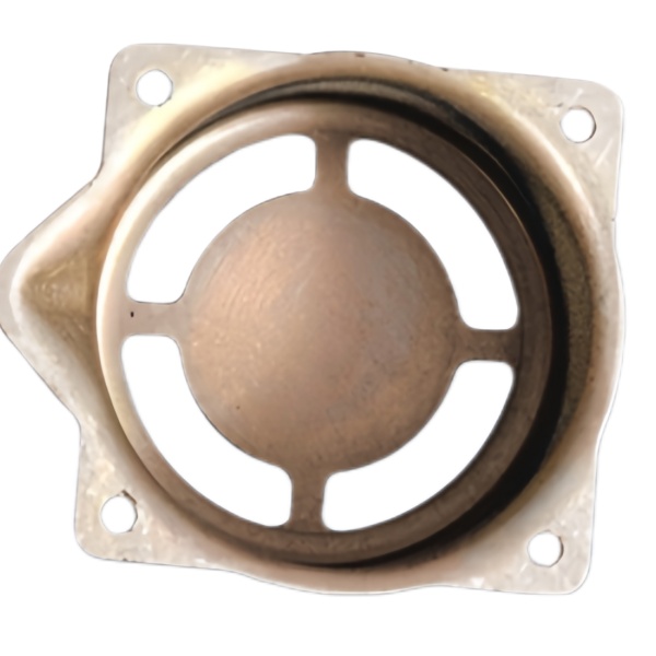
The Steel Deep Drawn Square Flanged Cover with Web is the geometry you get when a cover has to sit flat, bolt down around its perimeter, and refuse to drum under whatever is behind it — a shallow square shell with a wide mounting flange and a formed web of stiffening ribs across the floor. We draw these covers in carbon steel (SPCC / DC01) across our press range, and the engineering weight on this family sits in three places: the web that kills oil-canning, the flange that has to stay flat after everything the draw did to it, and the corner treatment that keeps a square cover from tearing as it forms.
Stiffening the web: rib geometry that stops oil-canning on a flat cover
A flat sheet-metal floor drums. Press on the middle of a large flat steel cover and it deflects elastically, snaps through, and radiates vibration into whatever it is mounted to — the behavior is called oil-canning, and it survives any thickness you can afford to specify. The cure is geometry: formed ribs across the floor raise the section’s second moment of area, and the floor stops moving. The ribs on this cover family run at 2 to 3 times material thickness in height, spaced so that no unribbed panel exceeds roughly 150 mm in free span, with rib-to-rib junctions tied rather than crossed loose — a tied grid behaves as one stiffened plate, while crossing ribs that merely intersect add stiffness in only one direction each.
Rib geometry has forming limits of its own. A rib taller than about 4 times material thickness in SPCC starts to thin at its crown and can split at the ends where the form runs out; we cap form depth at what the gauge will carry and recover the difference with rib frequency instead. Rib ends need runout radii — a rib that stops dead against flat sheet creates a crease that becomes a fatigue line. And the rib direction is drawn on the tool with the cover’s pressure side in mind: ribs parallel to the long span do the structural work, cross ribs tie the grid and carry the torsion. We form the complete web in the same die that draws the shell, one press stroke, so the rib pattern and the drawn geometry stay locked to each other and the tooling cost buys the whole feature at once.
The flatness budget on a square flange after forming
The flange is the mounting surface, and it is the feature the draw works hardest against. As the shell forms, the flange material flows inward unevenly — more from mid-edge than from the corners — and the flange that was flat on the blank comes off the punch with a waviness measured in whole millimeters if nothing controls it. We hold flatness on this family to 0.5 mm or better across the bolt line, and that number is manufactured, not hoped for: a blank holder sized to the flow distribution, corner relief in the blank shape, and where the spec is tight, a coining operation at the end of the forming sequence that flattens the flange between hardened surfaces under tonnage.
Bolt-hole positions compound the problem. Holes pierced in the blank before the draw move with the material flow — a hole 3 mm from the edge can shift a millimeter and elongate 10 percent where the flange stretched — so we pierce the bolt pattern after forming, located off the drawn internal profile, and the holes land within +/-0.15 mm of the formed geometry. Where a customer has pre-pierced holes in their drawing, we flag it at review with the honest two options: move the piercing downstream in our process, or open the hole tolerance and accept flow distortion. What we will not do is promise a pre-pierced hole position that the forming physics refuses to hold.
Corner radii on square flanged covers and the tearing they prevent
Every failure on a square cover concentrates at four points. The punch corner radius governs whether the material can wrap the corner without splitting: on SPCC in the 1.0 to 2.0 mm range we hold punch corner radii at 5 to 8 times thickness as standard, and when a drawing arrives with a tighter corner for styling reasons we negotiate it against real numbers — below 3 times thickness, corner thinning on a square flanged cover climbs past 20 percent and the scrap rate stops being a statistic and becomes a schedule. The die corner radius on the flange side matters equally: too tight and the flange material bunches into wrinkles at the corner root as it draws; too generous and the flange loses the crisp line the assembly wants.
Corner depth is the third variable. The distance from the flange to the flat floor at the corner is where the square cover either behaves like four gentle quarter-cylinders or like a deep box, and the transition matters because a shallow cover with generous corners draws in a single stroke with predictable thinning, while the same footprint an inch deeper wants staged drawing or corner relief cut into the blank. We evaluate the corner depth ratio on every new drawing in this family before quoting, because it is the single geometric number that most reliably predicts whether the cover is a one-die part or a two-die part.
Blank holder force and the wrinkles it has to prevent
On a square flanged cover, the blank holder is doing different jobs in different places. Mid-edge, the flange material needs to flow inward freely — too much holder force there stretches the flange instead of letting it feed, and the flange thins and then will not sit flat. At the corners, the same material is compressing as it converges, and too little holder force lets it buckle into corner wrinkles that then draw into the wall as locked-in defects no trim removes. The correct holder setting is a window between those two failure modes, and it is narrower on square geometry than round because the two regimes coexist on one perimeter.
We find the window empirically on the first article — bracket the force, draw test shells, read the flange and corner condition — and then lock the parameters into the setup sheet with tonnage readings recorded per run. Where the window proves too narrow for a given blank shape, the tool gets draw beads at the corners: local restrictions that meter the corner inflow deliberately, trading a few percent of additional draw force for the elimination of the wruckle failure mode. Beads are cut in our toolroom against the measured flow balance of the actual first-article, which is why we build the tryout parts into the tooling schedule rather than pretending the first production lot is the tryout.
How we verify flanged covers with a stiffening web
Each lot is released against the specific ways this geometry fails:
- Flange flatness on a surface plate or over the bolt line with the cover clamped at two diagonally opposite bolt positions — the constraint that mirrors real assembly — read against the 0.5 mm class flatness the drawing calls.
- Bolt-hole position and diameter, checked to the drawn internal profile datum the piercing used, sampled across the pattern including the corner holes where any residual flange distortion concentrates.
- Corner wall thickness on sampled parts at the punch radius zones, against the first-article reference and the thinning budget agreed at review.
- Web rib geometry: rib height and crown condition sampled by depth gauge, with rib ends inspected for creasing at the runout, since the rib terminations are where the stiffening either transfers into the floor or concentrates stress instead.
- Oil-can resistance on first article and periodic parts: point load applied at the center of the largest unribbed span, deflection measured against the drawing’s stiffness requirement where one is specified, or against the first-article benchmark where it is not.
- Surface and coating verification per the drawing’s finish callout, run after the forming checks so that any rework-causing defects are caught before the coating makes them expensive.
The sequence is deliberately ordered from geometry outward: flatness, holes, corners, ribs, stiffness, finish — the order in which a square flanged webbed cover actually fails in the field.
If you are comparing this part with a machined or welded alternative, the guide to deep drawn covers lays out where drawing wins, where it loses, and what it costs either way.
Specifications
| Item | Steel Deep Drawn Square Flanged Cover with Web |
|---|---|
| Brand | AUNOV |
| Designing | A drawing file or a physical sample starts the review, you get a DFM review together with the quotation. |
| Tooling | Dies engineered and produced in our own toolroom, held and maintained under your part number. |
| Samples | The first-article set ships with a full dimensional report and material certification. |
| Materials | Carbon steel (SPCC / DC01) leads the stock list for this part, alongside 304 / 316 stainless steel, aluminium, brass and copper, and the grade is fixed at the drawing review. |
| Surface finish | Plating, e-coat, powder coating, anodising or passivation, fixed at the drawing review. |
| Processing | Multi-stage drawing, annealed in line where wall thinning calls for it, then pierced and CNC-machined in house. |
| Equipment | Press capacity spans 5 to 500 T across mechanical and hydraulic lines, with CNC turning and milling cells and a climate-controlled CMM room. |
| Tolerance | +/-0.1 mm on as-drawn features, +/-0.03 mm on machined features. |
| Delivery terms | FOB is standard; DDP offered for EU and US, T/T and L/C accepted, D/P for established customers, call-off schedules supported. |
Related Products


Request a Quote for This Part
Send a drawing or sketch — get material advice, tooling cost and a per-piece price within 24 hours (working days).