
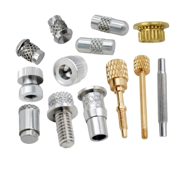
The Brass and Steel CNC Machined Knurled Grip Components are the class of part where a single feature — the knurl — carries most of the functional risk. The grip pattern has to close around the circumference, the forming operation has to leave the bore behind it usable, and the material choice between brass and steel changes which knurling method is even available. We cut these components on CNC turning centres with the knurl applied in-process, and this page covers the geometry and process decisions that separate a grip that feels solid from one that skips under torque.
Making the knurl pattern close around the grip diameter
A rolled knurl only looks continuous if the circumference divides evenly by the pitch. A 1.0 mm pitch straight knurl on a 12.00 mm diameter is trying to wrap 37.70 pitches around the part — the pattern lands 70 percent of a pitch off from itself on every revolution, and the result is a visible seam where the teeth collide. The fix is arithmetic, not luck: we set the pre-knurl diameter to the nearest whole number of pitches divided by pi. For that 1.0 mm pitch we would turn the blank to 12.06 mm (38 pitches) or 11.94 mm (37 pitches) before the wheels touch it, and the pattern closes on itself with no witness line.
Diamond patterns double the arithmetic because they are two straight knurls at an angle, typically 30 degrees to the axis. Both wheel sets have to divide the effective circumference, and the diagonal teeth intersect in a clean grid only when both pitches are compatible with the same finished diameter. When a drawing arrives with a diamond knurl specified on an awkward diameter, we adjust the diameter within its own tolerance band first; if the tolerance will not absorb the correction, we switch to a pitch that divides cleanly, and we say so on the manufacturability review that accompanies the quotation rather than quietly rolling a seam.
This closure discipline matters most on brass. The free-machining grades show every wheel mark, and a seam that would hide in a hardened steel surface under a black finish stands out on a polished brass grip as a visual defect that no amount of buffing removes.
Form knurling burnishes, cut knurling shaves: choosing per material
Form (or burnish) knurling displaces metal rather than removing it. The wheels are ground to the pitch, pressed into the rotating surface, and the material flows into the grooves — which work-hardens the surface, raises the effective diameter, and leaves a dense, smooth crest. It is fast, cheap and beautiful on ductile stock: C36000 brass form-knurls superbly, and mild steels through about 25 HRC behave. Past that hardness the wheels stop displacing and start smearing, crest definition collapses, and wheel life falls off a cliff.
Cut knurling shaves the pattern with wheels ground as cutting tools — sharper angle, actual clearance faces, chips produced. It runs slower, needs coolant, and costs more per minute, but it knurls material that burnishing cannot touch: hardened 1045 steel grips, stainless steel shafts, anything above roughly 30 HRC. It also does not swell the diameter the way forming does, which matters when the knurl sits between machined shoulders that were turned to final size in the same setup.
Our default for this product family: brass components get form knurling, steel components get cut knurling, and anything with a wall under 2 mm gets cut knurling regardless of material, because the radial squeeze of form wheels on a thin wall ovalls the bore behind the pattern. That last rule has saved more scrap than any other on this part class.
Material state matters as much as material type. Half-hard brass (H02) form-knurls with cleaner crests than full-hard, and where a customer specifies H02 for strength reasons we will form-knurl and verify bore distortion rather than argue; but the same part in H08 annealed condition swells unpredictably and gets cut knurling instead. Steel is the reverse: normalized 1045 burnishes acceptably, but a quenched-and-tempered shaft that a customer wants left at 40 HRC for wear life has to be cut, and the quotation reflects the slower cycle honestly instead of burying it.
Knurling moves metal: the diameter growth and the bore behind the pattern
Form knurling grows the outside diameter by roughly one knurl depth beyond the pre-knurl size — the material has to go somewhere, and it goes outward and inward in roughly equal measure. On a 1.0 mm pitch form knurl cut to 0.4 mm depth, expect 0.2 to 0.3 mm of diameter growth on the outside. That is fine for a grip diameter with a cosmetic tolerance, and it is a disaster for a grip that locates in a matching recess, so we pre-machine male locators on grips that have both: the locating diameter is turned after knurling, in a second operation, with the knurl used only for torque transfer.
The inward half of the displacement is the part nobody watches until it fails. On a hollow grip — a knob shell, a sleeve — the bore behind the knurl shrinks and often goes out of round by 0.05 mm or more, which shows up as a shaft that no longer slides through, or worse, an interference nobody designed. We sequence accordingly: bores that matter get finish-bored after the knurl, or the wall gets thickened at the design stage so the bore distortion stays below 0.02 mm. When we review a hollow knurled knob drawing, wall thickness under the pattern is the first number we check.
Overrun, chamfers and the shoulder the knurl runs into
A knurl wheel cannot stop on a dime — the last few teeth drag as the wheel lifts, and the pattern smears at the exit. Where the knurl runs up to a shoulder, we either cut an overrun groove 1.5 to 2 mm wide at the shoulder root, so the wheel disengages into empty air, or we chamfer the shoulder-side edge of the knurl zone at 30 degrees so the smeared exit teeth cut a clean transition instead of a rolled burr. The free end of the part gets a 0.5 to 1 mm chamfer ahead of the wheels for the same reason: an un-chamfered edge folds over on the first pass and drags a burr the entire length of the pattern.
Shoulder geometry also decides whether the knurl can run in the same setup as the turning. A sharp 90-degree shoulder with the knurl ending 0.5 mm short of it forces a tool change and a slow feed-out; a relieved shoulder with the knurl running into the undercut runs continuous, at full feed, and the cycle time drops by a quarter. We flag these choices on the review because they are the difference between a grip that costs what it should and one that pays tool-change penalties on every cycle for the life of the program.
How we verify knurled grip components on the shop floor
Grips are released against checks aimed specifically at the failure modes above:
- Pattern closure: visual inspection at 5× magnification over the full circumference for seam or skip, on every sampled part — a knurl that does not close is a process error, not a cosmetic one, because torque transfer concentrates at the seam.
- Post-knurl diameter: micrometer over the crests at three stations, checked against the growth predicted in the process plan, so drift in wheel pressure or material hardness shows up as a trend before it shows up as a rejected lot.
- Bore integrity on hollow grips: bore gauge or plug check after knurling, confirming the inward displacement stayed inside the designed distortion budget.
- Grip torque on sampled parts: the knob is mounted on a shaft of drawing-specified finish and size, and torque-to-slip is measured with a calibrated torque wrench. The acceptance value is agreed at first article — typically a minimum of twice the operating torque the grip will see in service.
- Surface condition: crest finish read visually against the first-article reference; brass parts additionally checked for smear or built-up material between the teeth, which is the early signature of a dull wheel.
Wheel condition itself is tracked as a consumable with a recorded life in parts; a wheel set that has rolled past its life gets changed at setup, not discovered in the inspection queue. The result is that when a lot of grips passes these checks, both the pattern arithmetic and the material displacement are verified as-run — the two things that actually go wrong on this part class.
The CNC Machining Parts range is the parent for parts like this one; tooling logic, finishing options and tolerance notes for the whole family are gathered on its overview page.
Specifications
| Item | Brass and Steel CNC Machined Knurled Grip Components |
|---|---|
| Brand | AUNOV |
| Designing | Send us your 2D drawing, or mail a sample for measurement, a manufacturability review comes back with the quotation. |
| Tooling | Our own toolroom designs and builds every die, with your part number on the tool record. |
| Samples | Samples for approval come with dimensional data and material certification. |
| Materials | Brass leads the stock list for this part, alongside carbon steel (SPCC / DC01), 304 / 316 stainless steel, aluminium and copper, per the drawing. |
| Surface finish | Finish options: plating, e-coat, powder coating, anodising or passivation, per your print. |
| Processing | Staged deep drawing, with in-line annealing where the draw ratio requires, with piercing and finish machining under the same roof. |
| Equipment | Our press floor runs 5-250 T mechanical and 250-500 T hydraulic presses, in-house CNC cells and a temperature-controlled inspection room. |
| Tolerance | As-drawn tolerance +/-0.1 mm, +/-0.03 mm after machining. |
| Delivery terms | Prices FOB, with DDP for EU and US on request, T/T and L/C accepted, D/P for established customers, blanket orders and call-offs supported. |
Related Products



Request a Quote for This Part
Send a drawing or sketch — get material advice, tooling cost and a per-piece price within 24 hours (working days).