
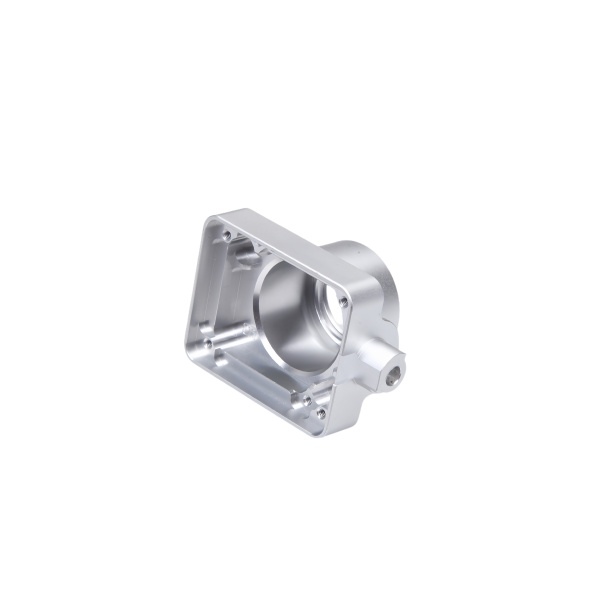
The Aluminum CNC Machined Mounting Bracket with Bore is a deceptively simple geometry: a body, a mounting pattern, and one bored hole that usually carries a bearing, a bush or a shaft. Everything interesting about the part happens in the relationship between that bore and the fastener pattern, because the bore defines where the shaft actually runs and the fasteners only define where the bracket sits. This page covers the datum logic we machine to, the tolerance stack between bore and bolt pattern, how the blank is chosen, and the verification that proves the assembly fits without a trial.
The bore is the datum, so the bracket is machined from it
A bracket drawing often dimensions the fastener pattern from the bracket’s outline, because outlines are easy to see. But the function of this part is to hold a rotating or sliding element in a fixed relationship to the structure, and the outline contributes nothing to that function. The engineering-correct scheme makes the bore the datum feature: hole position, alignment faces and fastener pattern are all dimensioned from the bore axis, and the outline is left inside a generous overall profile tolerance.
Machining follows the datum scheme rather than fighting it:
- The bore and its face are cut in the same setup as the alignment surfaces that the shaft system registers against, so their mutual relationship is never stacked across fixtures.
- The fastener pattern is then either cut in the same setup or located from a datum established by the bore – never from the outline, because outline position drifts with the blank.
- Where the print sends us outline-dimensioned geometry, we flag it at quotation and propose the datum re-dimension; the customer gains a tolerance they were unknowingly spending on an irrelevant feature.
The reward for this scheme is measurable: a bracket where the bore calls the datums can hold the bore-to-fastener-pattern relationship inside 0.05-0.1 mm of position without heroic effort, while an outline-dimensioned version of the same part has already spent that much before the bore is cut.
Position tolerance on the pattern is a stack problem the drawing must close
The classic failure on a bored bracket is an assembly that does not quite fit: the bore aligns to its shaft, but the fastener holes miss the tapped holes in the structure, or worse, the bolts fit and the bore is now offset from where the shaft needs it. The arithmetic lives in the positional tolerance chain between the bore, the fastener pattern and the mating structure’s own pattern. Fixed-fastener stack rules apply: the pattern-to-pattern tolerance must cover both halves’ errors plus clearance, and on a bracket like this the mating half is usually outside our control.
We resolve the chain explicitly with the customer:
- Establish which member carries the fasteners and which carries clearance holes, and calculate the minimum clearance that still assembles at worst-case tolerance positions.
- Convert the drawing’s coordinate tolerances to position callouts with MMC where the pins or bolts are the gauging features, because MMC buys real tolerance on clearance holes at zero cost to function.
- Hold the bore itself tight – position 0.05 mm or better relative to its datum system – and let the fastener pattern float at, say, 0.25 mm MMC, which is the economic distribution of precision: tight where the shaft runs, loose where the bolt merely clamps.
- Verify the bore at its actual mating size, not its nominal, because a bore at the top of its band locates a bearing differently than one at the bottom.
On 6061 aluminium, H7 bores for bearing fits are routine on our machining centres, and we hold surface finish at Ra 0.8 or better on the bore wall where a bearing runs, because finish and roundness together decide whether a light press seats quietly or frets.
Blank choice sets the price before any chip is cut
A bracket with a bored hub can begin as sawn plate, as extrusion, or as bar, and the differences are large enough to quote all three. Sawn plate is the default: cheap per kilo, available in every thickness, but it wastes the pockets and profile that machining must then remove, and thick plate carries rolling stress that can move a bracket after roughing. Extrusion is attractive when the bracket’s cross-section is constant – a profile with the hub pre-thickened and the web pre-thinned machines in a fraction of the time and removes nearly all of the stress-relief problem, at the cost of a custom extrusion die and a minimum mill quantity that only pays off above a few thousand parts per year. Bar suits small brackets whose hub diameter approaches the part’s largest dimension.
The rules we apply when quoting this family:
- Under roughly a thousand pieces, sawn plate plus rough-and-finish machining is almost always cheapest, because die amortization dominates any cycle-time saving.
- Above that volume with a constant section, extrusion typically cuts machining cost by 30-50% and holds flatness better, since most of the residual stress in plate is removed with the material that formed it.
- Roughing is planned with a rest pause before finishing on plate blanks, so stress rebalancing happens while there is still stock to correct it – the same discipline we hold on larger frames.
Tapped holes near the bore carry the load, and their depth is capped
The fastener holes on a bored bracket are not interchangeable: the ones nearest the bore clamp the load path, and on aluminium their thread depth and edge distance are genuine structural limits, not drafting details. In 6061-T6 a tapped M4 hole begins to strip at around 2.5 diameters of engaged thread, so specifying 3D of depth buys nothing but a broken tap and a scrapped part; conversely, under about 1.5D the thread becomes the weak link under vibration. Edge distance runs the same logic – a tapped hole closer than about 2.5-3 times its nominal diameter to the bore can bulge the bore wall when the bolt is torqued, and on a bore holding a bearing, bulge is interference you cannot see on a drawing.
- We form tapped holes with the film and coating plan already known: a bracket that will be anodized gets threads cut oversize or re-cut after coating, same rule as any anodized part.
- Thread depth is quoted as effective engaged thread, not drill depth, because the customer’s bolt only knows the first.
- Where vibration is in the duty cycle, we raise rolled versus cut threads at quotation – rolled threads are stronger in aluminium and cost a setup, which at volume is the right trade.
How we verify bore position and datum alignment on brackets
Verification on this family is an alignment exercise, because the part’s quality is relative geometry. Each release ships with:
- CMM alignment on the bore datum – the part is picked up on the bore axis and its face, then every other feature is reported relative to that frame, mirroring exactly how the bracket functions in service.
- Bore size, roundness and finish – size at multiple depths on the H7-type fits, roundness reported, and Ra on the bore wall verified by profilometry where the drawing specifies a bearing surface.
- Fastener pattern position reported at MMC where applicable, with actual positional values, so the customer can audit the stack rather than trust a pass/fail stamp.
- Thread verification by go/no-go gauges on a sampling plan, plus a depth check on the first article using the effective-thread criterion.
- Flatness of the mounting face over its full area, because a bowed face tilts the bore relative to the structure even when every hole is in position.
First articles carry the full report and the material certificate per heat; production batches run on the sampling plan agreed at approval with gauges referenced back to the CMM. The result is a bracket that assembles on the customer’s first attempt, with the numbers to explain why.
This part sits inside our CNC Machining Parts range. Across the cnc machining parts pages you will find the process notes, common materials and inspection points behind every product in the family.
Specifications
| Item | Aluminum CNC Machined Mounting Bracket with Bore |
|---|---|
| Brand | AUNOV |
| Designing | Send drawings, or send a sample to be measured, you get a DFM review together with the quotation. |
| Tooling | Tooling designed and cut in house, each die held against your part number. |
| Samples | Approval samples ship with a full dimensional report and material certification. |
| Materials | Aluminium is the primary stock for this part, alongside carbon steel (SPCC / DC01), 304 / 316 stainless steel, brass and copper, and the grade is fixed at the drawing review. |
| Surface finish | Plating, e-coat, powder coating, anodising or passivation, fixed at the drawing review. |
| Processing | Staged deep drawing, with in-line annealing where the draw ratio requires, then pierced and machined in house. |
| Equipment | Mechanical presses 5-250 T, hydraulic presses 250-500 T, CNC cells plus a temperature-controlled CMM room. |
| Tolerance | Drawn tolerances held to +/-0.1 mm, machined features held to +/-0.03 mm. |
| Delivery terms | FOB as standard, DDP available for EU and US destinations, T/T or L/C, D/P on repeat business, scheduled call-offs welcome. |
Related Products


Request a Quote for This Part
Send a drawing or sketch — get material advice, tooling cost and a per-piece price within 24 hours (working days).