
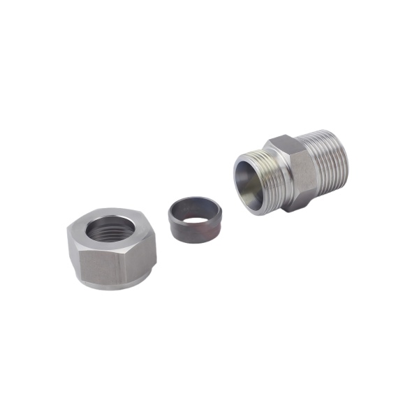
A compression fitting seals on the ferrule’s bite, so ferrule hardness and geometry decide everything
A compression fitting set—body, ferrule(s), and nut—seals when the nut’s axial force drives the ferrule into the body’s conical mouth, and the ferrule’s leading edge bites into the tube’s outer surface. The bite—plastic deformation of the tube by the ferrule edge—is what resists pull-out; the wedged ferrule-to-body cone is what seals. Both depend on the ferrule being hard enough to bite the tube but not so hard that it cracks instead of deforming.
For stainless steel compression fittings on stainless steel tube, we machine ferrules from 304 in a half-hard condition (H2 temper): hard enough to bite annealed tube, soft enough to swage into the body cone without splitting. The ferrule’s leading edge angle is typically 20–25°—a sharper edge bites deeper but concentrates stress and can crack on heavy-tube assemblies; a blunter edge may skid on the tube instead of biting. We hold the ferrule edge angle to ±0.5° and inspect the edge at 30× for burrs or rounded-over tips (either defect ruins the first-assembly bite, and a compression fitting that fails to bite on the first assembly will never grip properly thereafter).
Re-make behavior: what happens when the fitting is disassembled and re-tightened
Compression fittings in maintenance reality get disassembled—tubing replaced, instruments swapped. A well-designed set survives re-assembly: the ferrule stays swaged onto the tube, and re-tightening re-seats the existing ferrule in its original deformed position. The failure mode on re-make is over-tightening: the operator, unsure whether the joint is tight, adds another full turn, driving the ferrule deeper, over-biting the tube, and bulging the tube wall into the flow path (restriction) or splitting thin-wall tube.
We provide the re-assembly torque on the instruction sheet that ships with each set—typically 3/4 turn past finger-tight on first make, and snug-plus-1/8-turn on re-make—and we machine the nut’s friction surfaces (the nut’s thrust face and the ferrule’s back face) to a finish (Ra ≤ 1.6 µm) that makes the torque-to-bite relationship repeatable. A rough thrust face wastes 30–40 % of the applied torque as friction, which is exactly why operators over-tighten.
Body cone and tube stop geometry control ferrule placement
Inside the compression body, the conical seat and the tube stop (the shoulder that sets tube insertion depth) position the ferrule. If the cone angle is mismatched to the ferrule by more than 0.5°, the ferrule contacts only at its extreme edge or extreme back and neither bites nor seals properly.
We machine the body cone concentric to the tube bore within 0.02 mm TIR, with the cone surface at Ra ≤ 1.6 µm and free of circumferential tool marks (a spiral tool mark in the cone is a leak path under the ferrule). The tube stop is positioned so that with the tube fully home, the tube end stands 1–2 mm proud of the ferrule’s bite zone—guaranteeing the ferrule grips full-wall tube, not the tube’s cut end.
Gauge testing: the only assembly proof that a set truly grips
Dimensional inspection proves the parts; only a gauge test proves the assembly. Our standard for compression fitting sets:
- Assembly on gauge tube: Nut torqued per the first-make spec on a sample of gauge-quality tube (the same wall and temper specified for service).
- Gauge gap check: The nut’s gap-to-body (the visible thread gap between nut and body hex after tightening) is measured and recorded—this becomes the reference the installer can compare against in the field.
- Pressure hold: 1.5× rated pressure, 10 minutes, no leakage past ferrule or threads.
- Pull test: Axial pull at 1.5× the rated pull-out force (per the tube size’s rating); the tube must not move more than 0.1 mm. This directly proves the bite.
- Re-make test: Disassemble, re-make per re-assembly spec, repeat pressure hold. A set that passes first-make but leaks on re-make fails the batch test.
Material pairing across the set: body, ferrule, nut, and tube must be a matched system
A stainless steel compression set intended for stainless steel tube must not mix in a brass ferrule (too soft to bite stainless steel tube—it will collapse in the cone without gripping) or a much harder ferrule (will crack thin-wall tube at the bite). The set is a system:
- All-stainless steel (316 body/nut, 304 half-hard ferrule): The default for general industrial and chemical service. Ferrules are deliberately a slightly different grade and temper than the tube so the bite is a controlled deformation, not a galling contact.
- Brass set on copper or soft tube: Brass ferrule (half-hard) on annealed copper tube bites reliably; the same brass ferrule on stainless steel tube does not.
- Stainless Steel body with brass ferrule on stainless steel tube: A mix that occasionally appears on low-cost sets; it “seals” only until thermal cycling or vibration releases the un-gripped ferrule. We do not ship this combination, and we flag any drawing that implies it.
Parts like this one sit under the CNC Machining Parts range, whose overview page gathers the tooling logic, finishing options and tolerance notes shared across the family.
Ferrule seating: single versus double
A compression fitting seals on its ferrule, and the choice between a single and a double ferrule decides how forgiving the joint is. A single ferrule is simpler and cheaper but demands a cleaner tube end and a tighter torque; a double ferrule grabs the tube and resists vibration better at the cost of a more exact make-up. We recommend the ferrule from the service, vibratory or static, and we hold the nut and the body so the ferrule seats the same way every time. The fitting is only as good as the ferrule it was designed around, so we do not mix the two on a drawing and hope.
Tube-end prep the fitting cannot forgive
A compression fitting is half the joint; the tube end is the other half, and a tube that is cut square, deburred, and free of scratches is what the ferrule needs. We state the end prep on the fitting drawing because a ragged or bell-mouthed tube will not seal no matter how good the fitting is, and the failure gets blamed on the wrong half. We would rather put the prep on the print than ship a perfect fitting into a joint that was lost at the cut-off saw.
Specifications
| Item | Stainless Steel CNC Machined Compression Fitting Set |
|---|---|
| Brand | AUNOV |
| Designing | Send the drawing, or a sample we can measure, a manufacturability review comes back with the quotation. |
| Tooling | Dies designed and built in our own toolroom, held and maintained under your part number. |
| Samples | First-off samples are sent with a dimensional report plus material certs. |
| Materials | Stock for this part leads with 304 / 316 stainless steel, alongside carbon steel (SPCC / DC01), aluminium, brass and copper, and the grade is fixed at the drawing review. |
| Surface finish | Zinc, nickel or chrome plating, e-coat, powder coat, anodising or passivation, selected against the drawing requirement. |
| Processing | Multi-stage drawing, annealed in line where wall thinning calls for it, then pierced and CNC-machined in house. |
| Equipment | Press capacity from 5 to 500 T across mechanical and hydraulic lines, CNC cells plus a temperature-controlled CMM room. |
| Tolerance | Tolerances to +/-0.1 mm as drawn, with machined features to +/-0.03 mm. |
| Delivery terms | FOB as standard, DDP available for EU and US destinations, T/T and L/C; D/P on repeat accounts, call-off schedules and blanket orders supported. |
Related Products


Request a Quote for This Part
Send a drawing or sketch — get material advice, tooling cost and a per-piece price within 24 hours (working days).