
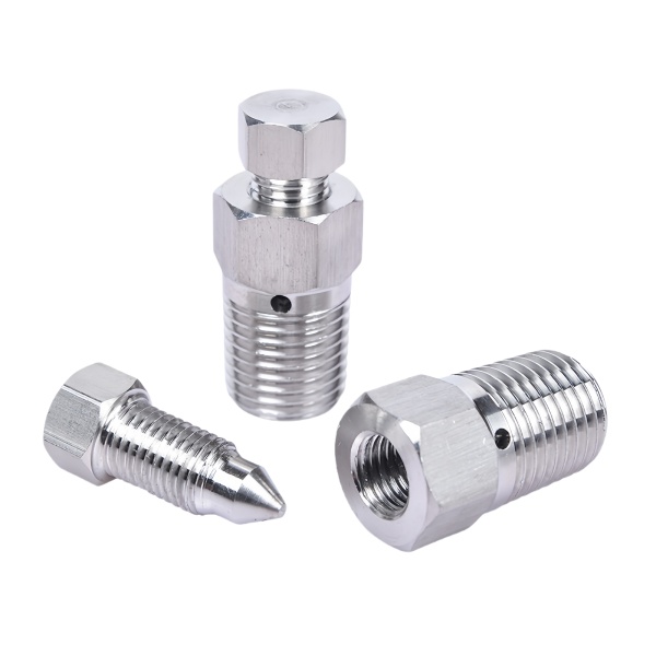
The orifice diameter tolerance governs flow: fourth-power sensitivity means small errors are big errors
An orifice nozzle plug—a plug with a calibrated flow hole—acts as a flow restrictor. For liquid flow through a sharp-edged orifice, the flow rate scales with the orifice area, which scales with diameter squared. In the laminar long-bore case (length/diameter > 4), the Hagen-Poiseuille relationship makes flow scale with diameter to the fourth power. Either way, orifice diameter is the single most flow-sensitive dimension on the part.
Concretely: a 1.00 mm orifice with a ±0.02 mm tolerance (a reasonable machining tolerance for a small drilled hole) carries a flow variation of ±4 % in the sharp-edge regime and ±8 % in the long-bore regime. If the customer’s flow spec is ±5 %, the long-bore design already fails on tolerance alone. We therefore drill orifices undersize (0.02–0.05 mm below nominal) and finish with reaming, or single-point bore on the lathe for larger sizes, holding diameter to ±0.005 mm up to 2 mm and ±0.01 mm above. Every orifice plug is flow-tested (below) so the certificate states measured flow, not just diameter.
Edge condition at the orifice entrance changes the discharge coefficient by up to 35 %
For a sharp-edged orifice, the discharge coefficient is ~0.61; a fully rounded entrance (radius = 20 % of orifice diameter) raises it to ~0.8–0.9, and a chamfered entrance lands in between. Two plugs with identical orifice diameters but different entrance edge conditions will flow differently by 20–35 %—more variation than the diameter tolerance itself.
We control the entrance edge by process choice: drilling leaves a slightly rounded, somewhat unpredictable edge (varies with drill wear); reaming produces a cleaner, more repeatable edge; and a separate lapping or ball-burnishing pass can deliberately generate a defined radius when the design calls for one. The drawing must specify the edge condition—”sharp edge, no chamfer” or “R0.1 entrance radius”—and we verify it at 30× magnification on the first article and every 50th part, because no dimensional gauge can distinguish these edges.
Plug thread must seal without contaminating the calibrated orifice
An orifice plug threads into a port, and the sealing method (thread sealant, crush washer, or O-ring) must not intrude on the orifice. Thread sealant paste squeezed past the last thread can partially occlude a 1 mm orifice, cutting flow by an unpredictable fraction that no inspection will catch until the system behaves wrong in the field.
We design orifice plugs with a seal that stays downstream of the orifice: a crush washer or O-ring on a shoulder behind the last full thread, so nothing flows toward the orifice except the fluid itself. Where a customer insists on dryseal threads (sealing on the thread flanks), we recommend the sealant be applied only to the first two threads (the end threads), so extrusion travels away from the orifice, and we note this on the installation sheet that ships with the plugs.
Clogging and erosion set the material choice and the maintenance interval
Fluid passing through a small orifice accelerates to high velocity—5–20 m/s is common in hydraulic restrictors. The orifice edge erodes over time, enlarging gradually and shifting the flow upward. In dirty fluids, particles lodge in the orifice and block it outright.
- 316 stainless steel: The baseline. Adequate erosion life for clean fluids; passivated interior resists corrosion products that would themselves plug the orifice.
- 17-4 PH (H900): Hardness HRC 40+ extends erosion life 3–5× over 316 in hydraulic service with marginal filtration. Our recommendation for continuous-duty restrictor plugs.
- Sintered-carbide or ruby orifice inserts: For orifices below 0.5 mm or extreme erosion service, we machine the stainless steel plug body and press in a carbide or sapphire/ruby jewel orifice—the insert carries the calibrated hole, and the stainless steel body is just the holder. This is the standard architecture for fuel injection and lubrication restrictors.
How we certify orifice plugs: every plug is flow-tested, not sampled
- Orifice measurement: Pin gauges (go/no-go) for size class, plus optical measurement on the first article to confirm diameter and edge condition.
- 100 % flow test: Every plug passes a calibration bench—test fluid at a specified pressure drop, flow measured by a calibrated flowmeter or timed gravimetric collection. Plugs are binned by measured flow if the customer accepts a binned distribution, or matched to nominal within the drawing tolerance if not.
- Direction marking: If the plug’s flow differs by direction (asymmetric entrance), the flow direction is marked on the hex with an arrow—an orifice plug installed backward can flow 25 % off spec with perfect-looking threads.
- Certificate: Each plug’s serial number, measured orifice diameter, and measured flow at the test condition go on the CoC. Customers use this data to match restrictors across parallel circuits without re-testing at receiving.
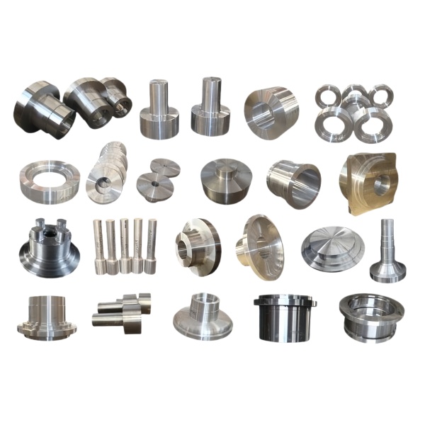
You will find this part in our CNC Machining Parts range. Process notes, common materials and inspection points for every product in the family are collected across the cnc machining parts pages.
Calibration record that travels with the plug
An orifice plug is a flow device, so its certificate matters as much as the part. We flow-test every plug, not a sample, and attach the measured bore and the resulting coefficient to the lot so the buyer knows the actual flow, not the nominal. The record travels with the shipment and is referenced on the bag, because an orifice installed on a nominal bore that drifted low is a system that under-performs and nobody can see why. We treat the flow number as the product and the metal as its carrier, which is the view a flow system actually needs.
Handling the calibrated orifice edge
The orifice edge is the precision surface, and it is also the most fragile, so the plug is packaged and handled so nothing touches the bore. We deburr the entrance to a controlled edge and then protect it, because a nick there changes the discharge coefficient more than a thou of diameter elsewhere. The thread that seals the plug is kept clear of the orifice so make-up torque never disturbs the flow edge, which is the detail that separates a calibrated orifice from a drilled hole with a certificate.
Specifications
| Item | Stainless Steel CNC Machined Orifice Nozzle Plugs |
|---|---|
| Brand | AUNOV |
| Designing | Send us your 2D drawing, or mail a sample for measurement, our engineers reply with a manufacturability assessment and pricing. |
| Tooling | Dies engineered and produced in our own toolroom, with your part number on the tool record. |
| Samples | First articles go out with a dimensional report plus material certs. |
| Materials | 304 / 316 stainless steel leads the stock list for this part, alongside carbon steel (SPCC / DC01), aluminium, brass and copper, with grade selection confirmed at drawing review. |
| Surface finish | Zinc, nickel or chrome plating, e-coat, powder coat, anodising or passivation, each selected against the drawing requirement. |
| Processing | Multi-stage drawing, annealed in line where wall thinning calls for it, then pierced and CNC-machined in house. |
| Equipment | Mechanical presses 5-250 T and hydraulic presses 250-500 T, in-house CNC cells and a temperature-controlled inspection room. |
| Tolerance | Drawn tolerances held to +/-0.1 mm, +/-0.03 mm on machined surfaces. |
| Delivery terms | FOB standard, DDP offered for EU and US, T/T and L/C; D/P on repeat accounts, call-off scheduling supported. |
Related Products


Request a Quote for This Part
Send a drawing or sketch — get material advice, tooling cost and a per-piece price within 24 hours (working days).