
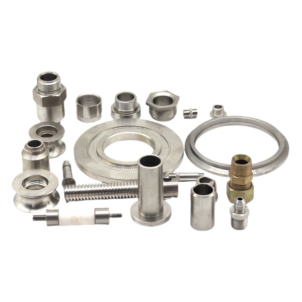
Bushing wall thickness and material choice determine whether the bushing carries load or deforms out of round
A machined bushing—a plain bearing, a spacer sleeve, or a guide ring—transmits radial load from a shaft to a housing through its wall. The wall must be thick enough to carry the bearing pressure without yielding (plastic deformation that would close the bore onto the shaft) but not so thick that it wastes material and space.
The standard design calculation is p = F / (D × L), where F is the radial load, D is the bushing bore diameter, and L is the bushing length. For brass (C36000, yield ~120 MPa), a 20 mm bore × 25 mm long bushing carrying 1500 N has a bearing pressure of 1500 / (20 × 25) = 3 MPa—well below the 15–20 MPa allowable for bronze/brass in boundary-lubricated service. The same bushing in steel (1045, yield ~350 MPa) could carry 5–8× the load before approaching its limit, but steel-on-steel sliding contact galls unless lubrication is continuous.
We machine bushings with a wall thickness of at least 5 % of the bore diameter for load-carrying bushings (e.g., 1 mm minimum wall for a 20 mm bore) and 2.5 % for spacer bushings that carry no radial load. Below these ratios, the bushing becomes flexible enough that insertion forces (pressing into the housing) ovalize it, and it no longer maintains a round bore.
Ring gear concentricity to its mounting datum determines the transmission’s backlash variation
A ring gear—an internal gear or a gear ring bolted to a hub—must be concentric with the shaft or housing it drives. Eccentricity between the gear pitch circle and the mounting datum produces once-per-revolution variation in backlash and center distance. In a gearbox with 0.05 mm of ring gear eccentricity, the effective center distance varies by ±0.05 mm, which changes the backlash by roughly 2 × 0.05 × tan(20°) = 0.036 mm per revolution. For a precision gearbox with a specified backlash of 0.05–0.10 mm, this variation is 36–72 % of the total—unacceptable.
We hold ring gear concentricity (pitch circle to mounting datum) to 0.02 mm TIR by machining the gear teeth and the mounting bore in the same setup, indexed from a common datum. For gears that are hobbed after the mounting bore is finished (the more common sequence when the bore is the first operation), we verify concentricity by mounting the gear on a precision arbor and measuring the pitch circle runout with a master pin between teeth. Gears exceeding 0.02 mm are re-chucked and lightly re-hobbed (0.05 mm radial stock removal) to correct the offset.
Brass vs. steel for gears in low-load applications: noise and corrosion often decide, not strength
For small gears in instruments, appliances, and light-duty mechanisms, both brass and steel can meet the strength requirements easily. The practical selection then hinges on other factors:
- Choose brass (C36000): When quiet operation matters (brass’s lower modulus damps tooth impact sounds); when the gear meshes with a steel pinion and the dissimilar-metal pair resists galling (brass-on-steel is a classic bearing combination); when the gear will be visible and golden appearance is desired; when corrosion resistance is needed without plating (brass self-passivates). Cost: moderate raw material, but machining speed is high (C36000 machines 135 % of steel speed), so unit cost is competitive.
- Choose steel (1045 or 4140): When the gear will be heat-treated for wear resistance (brass cannot be hardened); when torque is high enough that brass’s 120 MPa yield is marginal (steel yields at 350–600 MPa); when the gear meshes with a brass or plastic gear and the harder steel member extends the pair’s life (steel-on-brass wears the brass, but slowly; steel-on-steel without lubrication galls and fails quickly).
- Choose 303 stainless steel: When corrosion is a concern (food equipment, marine, medical) and plating is not acceptable (plating buildup affects tooth geometry). Machines nearly as well as carbon steel and needs no surface treatment for moderate corrosion environments.
Interference fit between the bushing and housing must be calculated to survive thermal cycling
A bushing pressed into a housing with interference relies on the friction from the interference to prevent rotation and axial movement. The interference creates radial pressure between the bushing OD and the housing bore. When temperature changes, the pressure changes because the bushing and housing expand at different rates (if different materials) or because the interference relaxes via creep at elevated temperature.
The critical case is a brass bushing in an aluminum housing: brass CTE ≈ 20 µm/m·K, aluminum CTE ≈ 23 µm/m·K. When heated, the aluminum housing expands slightly more than the brass bushing—actually helping maintain interference at high temperature. But at low temperature, the aluminum contracts more than the brass, and a 40 °C drop reduces the interference on a 25 mm bushing by 25 × 3 × 10⁻⁶ × 40 = 0.003 mm. If the design interference was only 0.008 mm (minimum press-fit for 25 mm diameter), the cold-temperature interference drops to 0.005 mm—still positive but with reduced retention force. We specify a minimum interference of 0.012 mm for brass-in-aluminum bushings subjected to thermal cycling, verified by measuring the bushing OD and housing bore on the first article and every 50th part.
How we verify rings, gears, and bushings before shipping an assorted order
For assorted orders containing multiple component types:
- Bushings: 100 % go/no-go on bore (plug gauge) and OD (ring gauge). Sample measurement (every 20th) with micrometer for actual size and ovality. Bore surface finish (Ra ≤ 1.6 µm turned, ≤ 0.8 µm reamed) verified on first article.
- Rings: Flatness of both faces (0.02 mm TIR on granite plate). OD-to-ID concentricity (0.02 mm TIR on CMM or V-block + indicator). Wall thickness variation around circumference (< 0.03 mm).
- Gears: Pitch diameter and tooth thickness (measurement over pins, perAGMA method). Concentricity to mounting bore (0.02 mm TIR as described above). Tooth surface finish (visual + Ra sample on one tooth per batch). Hardness (if heat-treated: Rockwell per drawing spec).
- Material verification: Mill test report per alloy (C36000 brass, 1045 steel, 303 stainless steel). Segregation check: brass parts weighed vs. steel parts (brass is ~15 % denser; weight sorting catches gross mix-ups).
- Packaging: Each component type bagged separately with part number, alloy, and quantity on the label. Assorted orders include a photo reference sheet showing each part next to a scale.
You will find this part in our CNC Machining Parts range. Process notes, common materials and inspection points for every product in the family are collected across the cnc machining parts pages.
Specifications
| Item | Brass and Steel CNC Machined Rings Gears and Bushings |
|---|---|
| Brand | AUNOV |
| Designing | Send us your 2D drawing, or mail a bushing sample for measurement, you get a DFM review together with the quotation. |
| Tooling | Every die designed and built in our toolroom, each die held against your part number. |
| Samples | First articles go out with dimensional data and material certification. |
| Materials | Brass leads the stock list for this part, alongside carbon steel (SPCC / DC01), 304 / 316 stainless steel, aluminium and copper, with the final grade confirmed at the drawing review. |
| Surface finish | Plating, e-coat, powder coating, anodising or passivation, selected against the drawing requirement. |
| Processing | Staged deep drawing, with in-line annealing where the draw ratio requires, then pierced and machined in house. |
| Equipment | Our press floor runs 5-250 T mechanical and 250-500 T hydraulic presses, CNC turning centres and a climate-controlled CMM room. |
| Tolerance | +/-0.1 mm on as-drawn features, +/-0.03 mm on machined surfaces. |
| Delivery terms | FOB is standard; DDP offered for EU and US, T/T and L/C accepted, D/P for established customers, call-off schedules supported. |
Related Products


Request a Quote for This Part
Send a drawing or sketch — get material advice, tooling cost and a per-piece price within 24 hours (working days).