
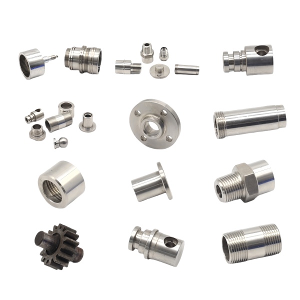
Flange face flatness and perpendicularity to the bore axis are the two parameters that prevent leakage at the gasket interface
A machined flange—whether it is a pipe flange, a pump flange, a valve body flange, or a manway cover—seals against its mating component through a gasket (or metal-to-metal contact) at the flange face. The quality of this seal depends on two geometric factors: how flat the face is, and how perpendicular it is to the bore/passage axis.
Flatness: We machine flange faces to 0.01 mm TIR over the gasket area for standard applications and 0.003 mm TIR for metal-to-metal seals or pressures above 20 MPa. Flatness is achieved by a facing operation with a large-diameter face mill taking a light finishing pass (0.05–0.10 mm depth of cut) after all other machining is complete. The part remains clamped in the same setup as the bore to ensure perpendicularity.
Perpendicularity: The flange face must be within 0.5° of perpendicular to the bore axis (0.3° for pressures > 10 MPa). This ensures that when the flange is bolted to its mate, the clamping force is distributed uniformly around the gasket circumference rather than concentrated on one side. A 1° angular error on a 100 mm diameter flange produces a gap variation of 0.87 mm across the diameter—enough to cause immediate leakage even with a compliant gasket.
Gear tooth profile accuracy determines noise level, efficiency, and service life more than material strength does
A machined gear (spur, helical, bevel, or internal) transmits power through the rolling and sliding contact of its teeth. The accuracy of the tooth profile—the deviation from the theoretical involute curve—determines three performance characteristics simultaneously:
- Noise: Profile error creates impact between mating teeth as they enter and exit mesh. Each impact generates an audible “gear whine” at the tooth-meshing frequency (teeth × RPM / 60). A gear with AGMA Q8 profile accuracy (typical for commercial machining) produces acceptable noise levels for most industrial applications. AGMA Q12 (precision ground) is needed for quiet operation in automotive and HVAC applications.
- Efficiency: Profile error increases sliding friction between teeth because the contact point deviates from the theoretical line of action. The efficiency loss is typically 1–3 % per quality grade below optimal. For a 95 % efficient gearbox at Q8, dropping to Q6 might reduce efficiency to 91–92 %—significant over the equipment’s operating life in terms of energy cost.
- Life: Profile error concentrates load at the tip or root of the tooth rather than distributing it across the full active profile. This localized loading increases contact stress by 1.5–2× and reduces fatigue life by 3–5× compared to a perfectly profiled gear.
We produce gears by hobbing (for Q7–Q9 accuracy, most common for machined-from-solid gears), shaping (for internal gears and some special profiles), or grinding (for Q10–Q12 precision). Hobbing is our default process for stainless steel gears up to module 4; it produces consistent profile accuracy at reasonable cost (~0.05–0.15 USD/tooth depending on size and material).
Coupling hub bore tolerance relative to the shaft fit class determines both assembly force and runout
The bore of a coupling hub—whether it is a flexible disc coupling, a jaw coupling, a gear coupling, or a rigid sleeve coupling—is the critical interface that connects the coupling to the shaft. The fit class (clearance, transition, or interference) determines:
- Assembly force: Interference fits require press or thermal assembly; clearance fits assemble by hand. Transition fits may require light pressing depending on where each part falls within its tolerance band.
- Runout contribution: A loose clearance fit allows the hub to shift slightly off-center under vibration or during torque reversal, adding 0.01–0.03 mm of runout that was not present when the coupling was initially aligned. An interference or line-to-line fit minimizes this contribution.
- Serviceability: Clearance-fit hubs can be removed without heating or special tools. Interference-fit hubs may require induction heating or hydraulic removal—a consideration for field maintenance.
We machine coupling bores to H6 (+0.009/0 at 25 mm) as default for precision couplings and H7 (+0.021/0) for general-purpose couplings. For high-speed couplings (>3000 RPM), we add a ground finish to the bore (Ra ≤ 0.4 µm) to reduce the coefficient of friction and make future removal easier if needed.
Stainless steel selection between 304, 316, and 17-4 PH for these components depends on corrosion environment and strength requirement
The “stainless steel” designation covers a family of alloys with significantly different properties:
- 304 (AISI 304/EN 1.4301): 18 Cr / 8 Ni. Good general-purpose stainless steel. Excellent corrosion resistance in fresh water, fuels, oils, and most organic chemicals. Not suitable for seawater or chloride-rich environments (pitting risk above ~200 ppm chlorides). Machines adequately (work-hardens; requires sharp tools). Lowest cost of the three. Default choice unless 316 or 17-4 PH is specified.
- 316 (AISI 316/EN 1.4401): 18 Cr / 10 Ni / 2-3 Mo. Molybdenum addition provides superior pitting resistance in chloride environments. Used for marine hardware, chemical processing equipment, and any application involving saltwater or chlorinated cleaners. Machines similarly to 304 (slightly more tool wear due to molybdenum carbides). Cost: ~10–15 % higher than 304.
- 17-4 PH (AISI 630/EN 1.4542): Precipitation-hardening stainless steel. Supplied soft (solution-annealed, ~HRC 33) for easy machining, then heat-treated to H900 (HRC 38–43) or H1020 (HRC 44–48) for final use. Strength roughly 2–3× annealed 316. Used for gears, coupling hubs, and flanges where high strength in a small envelope is required. Excellent machinability in the annealed condition. Cost: ~2–3× 304 due to lower production volume and specialized heat treatment.
How we verify gear-coupling-flange assemblies before shipping as integrated units
When the order includes multiple component types (gear + coupling + flange) that must work together:
- Individual component inspection: Each part meets its own drawing before assembly. Gear: profile check (lead and profile error), pitch diameter measurement, hardness verification. Coupling: bore size, balance check (if required), flexibility element inspection. Flange: face flatness, bolt circle diameter, gasket surface finish.
- Mating verification: Gear meshes with master gear (or mating gear if supplied) under blue compound; contact pattern checked for center position and coverage (> 70 % of face width, centered). Coupling bore test-fits on master shaft; confirms fit class and runout (< 0.02 mm TIR). Flange bolted to master flange; gap feeler-gauged around circumference (< 0.05 mm max variation).
- Assembly drawing update: If we assemble the components into a unit before shipping, we generate an assembly drawing showing actual measured values (not just nominals) for all interfacing dimensions. This helps the customer’s receiving inspection understand what to expect.
- Preservation: Gears receive rust-preventive oil on teeth (unless the customer specifies dry shipment). Coupling flexible elements are covered to protect from UV and ozone. Flange faces get removable protective film. All stainless steel parts are passivated per ASTM A967 before shipment.
CNC Machining Parts is the parent range for parts like this one; the overview page gathers the tooling logic, finishing options and tolerance notes that apply across the family.
Specifications
| Item | Stainless Steel CNC Machined Couplings Flanges and Gears |
|---|---|
| Brand | AUNOV |
| Designing | Send drawings, or send a sample to be measured, you get a DFM review together with the quotation. |
| Tooling | Tooling designed and cut in house, held and maintained under your part number. |
| Samples | First articles go out with a full dimensional report and material certification. |
| Materials | Stock for this part leads with 304 / 316 stainless steel, alongside carbon steel (SPCC / DC01), aluminium, brass and copper, and the grade is fixed at the drawing review. |
| Surface finish | Plating, e-coat, powder coating, anodising or passivation, selected against the drawing requirement. |
| Processing | Deep drawing in stages, in-line annealing where needed, then pierced and CNC-machined in house. |
| Equipment | Mechanical presses 5-250 T, hydraulic presses 250-500 T, CNC turning and milling cells, a climate-controlled CMM room. |
| Tolerance | Drawn tolerances held to +/-0.1 mm, +/-0.03 mm after machining. |
| Delivery terms | Standard terms FOB, DDP offered to EU and US, T/T and L/C accepted, D/P for established customers, blanket orders and call-offs supported. |
Related Products


Request a Quote for This Part
Send a drawing or sketch — get material advice, tooling cost and a per-piece price within 24 hours (working days).