
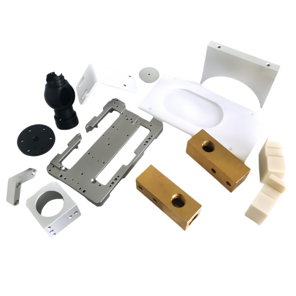
Plate-bracket stiffness under bending determines whether the assembly maintains alignment or deflects under load
A machined plate that also functions as a structural bracket—supporting a motor, a sensor, a bearing block, or a sub-assembly—must resist bending deflection under the applied load. The deflection is determined by the plate’s material (Young’s modulus), thickness, and the span between support points. For a simply supported rectangular plate with a central point load, the maximum deflection is δ = F × L³ / (48 × E × I), where L is the span, E is Young’s modulus, and I is the area moment of inertia (t × w³ / 12 for a plate of thickness t and width w).
The practical implication: doubling the plate thickness reduces deflection by a factor of 8 (because I scales with t³). This means that increasing a bracket plate from 3 mm to 6 mm thick reduces its deflection under the same load from, say, 0.2 mm to 0.025 mm—often the difference between acceptable and unacceptable for precision assemblies where 0.1 mm of deflection would misalign a shaft coupling or a sensor target.
Hole position tolerance on the bracket relative to the mating component’s hole pattern determines whether bolts can be inserted without forcing
The most common assembly issue with machined brackets is not dimensional inaccuracy in the bracket itself but positional mismatch between the bracket’s hole pattern and the hole pattern on the component it mounts to. If both parts are manufactured at their respective tolerance limits in opposite directions, the worst-case positional error is the root-sum-square of both tolerances.
For example: a bracket with two mounting holes at 100 ±0.1 mm pitch mounting to a motor face with holes at 100 ±0.15 mm pitch. Worst-case mismatch = √(0.1² + 0.15²) = 0.18 mm. For an M6 bolt with 0.5 mm clearance (7 mm bolt in 6.5 mm hole), this 0.18 mm error consumes 36 % of the available clearance—still workable but requiring the assembler to “wiggle” the bracket during bolt insertion. If the same bracket had M4 bolts with 0.3 mm clearance (4.5 mm bolt in 4.2 mm hole), the 0.18 mm error would consume 60 % of the clearance, and some assemblies would require forceful alignment that introduces assembly stress into the bracket.
We address this by machining our bracket hole positions to the tighter end of the drawing tolerance (aiming for nominal rather than the limit) and by adding a note on the traveler recommending that the customer hold their mating part’s hole pattern to no looser than half the drawing tolerance if close-clearance assembly is expected.
The interface between the metal bracket and any attached plastic component must accommodate CTE mismatch
When a plastic part (an electronics enclosure section, a cable guide, a handle, or a display bezel) attaches to a machined metal bracket via screws, rivets, or snap features, the differential thermal expansion between aluminum (CTE ≈ 23 µm/m·K) and typical engineering plastics (CTE ≈ 80–120 µm/m·K) creates relative movement as temperature changes. Over a 40 °C temperature swing (common between indoor storage and outdoor sun exposure), a 100 mm long plastic part will grow roughly 0.32–0.48 mm more than the aluminum bracket it attaches to.
If the attachment method does not allow for this relative movement—such as a rigid screw connection at both ends with no slotted holes—the result is either buckling of the plastic part (if it expands more than the bracket) or tensile stress in the plastic (if it contracts more). Either condition can cause cracking after enough thermal cycles. We design the attachment with one “fixed” end (precisely located hole or feature) and one “floating” end (slotted hole, oversized clearance, or compliant clip) that allows ±0.5–1.0 mm of relative movement without transmitting stress to the plastic part.
Surface treatment selection for mixed-material brackets considers both the metal and the adjacent plastic
A bracket that mates with plastic components must consider how its surface treatment affects the plastic:
- Bare aluminum: No chemical interaction with plastics. Will oxidize over time (cosmetic only; does not affect function). Lowest cost. Default choice unless corrosion resistance or appearance requires otherwise.
- Anodize (Type II): Excellent for aluminum corrosion protection. The oxide layer is inert and does not interact with plastics. However, anodize adds thickness (10–25 µm per side) which changes critical dimensions slightly—we account for this by machining the part 20–50 µm undersized before anodizing if dimensions are at the limit of the tolerance band.
- Chromate conversion coating (Alodine/ Iridite): Thin (0.5–3 µm), provides good corrosion resistance for indoor use, and most importantly provides an excellent bonding surface for adhesives. If the plastic part is bonded to the bracket (epoxy, acrylic adhesive, or double-sided tape), chromate conversion is preferred over anodize because the anodized surface is porous and may absorb adhesive unevenly.
- Powder coat: Thick (60–80 µm), durable, available in any color. Good for visible brackets where appearance matters. The main consideration for plastic-mating applications is that powder coat adds significant thickness and may interfere with close-tolerance fits. We mask all fitting surfaces before powder coating to maintain dimensional accuracy.
How we manage mixed-material orders where plates, brackets, and plastic parts ship as a kit
“Mixed CNC machined plates brackets and plastic parts” orders are essentially kit orders: we machine the metal components, source or receive the plastic components, and ship them together as a matched set. Our kitting process:
- Receive and inspect plastic parts: Count, visual check, and dimensional spot-check (critical interfacing dimensions) against the customer’s specification or drawing. Any out-of-spec plastic parts are segregated and reported before we begin metal machining (so we can adjust our targets if needed).
- Machine metal parts to match: Using the measured plastic-part data, we set our machining targets as described earlier (center of combined tolerance zone). First-article metal parts are test-assembled with sample plastic parts before production continues.
- Kit assembly verification: One complete kit (all metal + all plastic parts for one assembly) is fully assembled by our QC technician. Photos and measurements document the assembly. This kit serves as the “golden sample” for the batch.
- Packaging: Metal and plastic parts are bagged separately within the kit box (to prevent scratching of plastic by sharp metal edges) but labeled with the same kit/assembly number. A packing list identifies which metal parts go with which plastic parts.
- Certificate of Conformance: Lists all metal parts with their material certs and dimensional data, plus a statement that plastic parts were received inspected and found conforming to the customer’s specification (with the actual measurement data attached).
Parts like this one sit under the CNC Machining Parts range, whose overview page gathers the tooling logic, finishing options and tolerance notes shared across the family.
Specifications
| Item | Mixed CNC Machined Plates Brackets and Plastic Parts |
|---|---|
| Brand | AUNOV |
| Designing | A drawing file or a physical sample starts the review, DFM feedback is returned with the quote. |
| Tooling | Our own toolroom designs and builds every die, each die held against your part number. |
| Samples | First-off samples are sent with a dimensional report and material certificate. |
| Materials | Materials held: carbon steel (SPCC / DC01), 304 / 316 stainless steel, aluminium, brass, copper, with grade selection confirmed at drawing review. |
| Surface finish | Finish options: plating, e-coat, powder coating, anodising or passivation, as called out on your print. |
| Processing | Deep drawing in stages, in-line annealing where needed, then pierced and CNC-machined in house. |
| Equipment | Our press floor runs 5-250 T mechanical and 250-500 T hydraulic presses, CNC cells plus a temperature-controlled CMM room. |
| Tolerance | Drawn tolerances held to +/-0.1 mm, with machined features to +/-0.03 mm. |
| Delivery terms | Standard terms FOB, DDP offered to EU and US, T/T and L/C accepted, D/P for established customers, call-off schedules and blanket orders supported. |
Related Products



Request a Quote for This Part
Send a drawing or sketch — get material advice, tooling cost and a per-piece price within 24 hours (working days).