
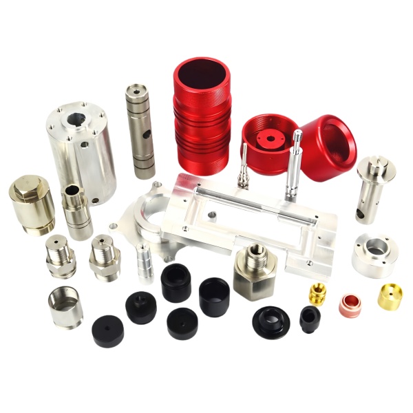
Red anodize color consistency is the most common customer complaint—and the most preventable
Among all anodize colors, red is the most difficult to control and the most likely to generate customer returns for “color mismatch.” The reason is physiological: the human eye has its highest color discrimination sensitivity in the yellow-red region of the spectrum (560–700 nm), meaning that a ΔE difference of 1.0 in red is clearly visible to an average observer, whereas the same ΔE difference in blue or green may go unnoticed. Red organic dyes also tend to have narrower absorption peaks than blue or black dyes, making the final color more sensitive to variations in dye concentration, bath temperature, and anodize layer thickness.
Our red anodize process control plan includes:
- Anodize layer thickness: held to 12 ±1 µm (tighter than the standard 10–15 µm range) because layer thickness directly affects red dye loading. Thicker layers absorb more dye and appear deeper red; thinner layers appear orange-red or pink.
- Dye bath: maintained at 55 ±1 °C with concentration verified by spectrophotometric absorbance at the dye’s peak wavelength (typically 520–540 nm for red dyes) every 2 hours. Bath life is limited to 20 square meters of parts per liter of solution; beyond this, dye depletion causes a systematic shift toward lighter shades.
- Dye time: adjusted based on measured layer thickness. Parts at 11 µm get 12 minutes; parts at 13 µm get 9 minutes. This inverse compensation keeps the total dye uptake roughly constant across the allowable thickness range.
- Color verification: every part is visually compared to a master sample under D65 (daylight-balanced) lighting. Every tenth part is measured with a spectrophotometer, and the batch mean ΔE must be below 1.5 relative to the master.
The relationship between anodize thickness and dye color means pre-plate dimensions must be adjusted per-color
Because we hold red anodize to a tighter thickness band (12 ±1 µm) than natural or black anodize, the pre-plate machining offset must be calculated accordingly. A feature with a post-plate target of 10.000 ±0.01 mm must be machined to 10.024 ±0.005 mm before anodizing (accounting for 12 µm per side × 2 sides = 24 µm total). If the same part were to be natural anodized with a 15 µm layer, the pre-plate dimension would be 10.030 mm—a 6 µm difference that matters for press-fit features and threaded holes.
We maintain separate machining offset tables for each color/finish combination: natural (15 µm), black (12 µm), red (12 µm), clear (10 µm), and hard coat (50 µm). The CNC programmer selects the correct offset table based on the traveler’s finish callout, and the first article inspection confirms that the as-anodized dimensions fall within spec. Using the wrong offset table is the most common cause of out-of-tolerance features on anodized parts—it does not affect the machined dimension (which passes pre-plate inspection) but causes the part to fail final inspection after anodizing.
Machined surface texture shows through thin anodize layers and affects the final appearance
The appearance of a colored anodized part is not determined solely by the dye—it is also affected by the underlying machined surface texture. A surface with prominent tool marks (visible feed lines from a worn insert or an aggressive feed rate) will show those marks through the anodize layer as subtle light-and-dark bands parallel to the tool path direction. This effect is most noticeable on red and blue anodize (where the eye’s contrast sensitivity is high) and least noticeable on black anodize (where the dark color masks most texture variation).
We specify a maximum surface roughness of Ra 1.6 µm on all surfaces that will receive colored anodize, and Ra 0.8 µm on “A-surface” (cosmetically critical) areas. This is achieved by using a wiper insert for the finishing pass (which produces a smoother surface than a standard insert at the same feed rate) and by avoiding stop marks (the small ridge left when a tool pauses mid-pass). For flat cosmetic surfaces, we add a single-point flycut pass across the entire face at 200 mm/min feed with a polished diamond insert, which produces a mirror-like finish (Ra 0.2–0.4 µm) that shows absolutely uniform color after anodizing.
Hard anodize vs. decorative anodize: choosing based on function, not just appearance
“Red anodized” can refer to two very different processes: decorative Type II anodize (thin, 10–15 µm, dyed, sealed) and hard coat Type III anodize (thick, 25–50 µm or more, often left undyed or lightly dyed). Customers who specify “red anodize” without specifying the type sometimes expect the wear resistance of hard coat while wanting the deep color of decorative anodize—and the two are partially incompatible because thick hard-coat layers scatter light more strongly and produce a muted, cloudy color compared to the bright, saturated color of thin decorative anodize.
We help customers choose by asking three questions:
- Will the part experience abrasive wear or sliding contact? If yes → hard coat (Type III), accept muted color or consider a colored topcoat over the hard coat.
- Is the primary requirement visual appearance? If yes → decorative (Type II), specify wear expectations so we can confirm that Type II will survive the service environment.
- Does the part need electrical insulation? Hard coat provides dielectric strength of 800–1500 V/0.001 inch; decorative anodize provides only 200–400 V/0.001 inch. If electrical isolation is required, hard coat is necessary regardless of color preference.
For the “assorted red anodized parts” category that this product represents, the answer is almost always decorative Type II with emphasis on color consistency, because these parts are primarily visual/structural rather than wear surfaces.
Masking requirements for red anodize add cost and lead time—plan them into the drawing
If certain features of a red-anodized part must remain unanodized (threaded holes that will be assembled with locking compound, bearing seats that require precise fit, or electrical contact points that need bare metal conductivity), those features must be masked before anodizing. Masking adds cost (labor + mask material) and introduces risk: if the mask leaks even slightly, a thin oxide layer forms in the “unmasked” area and interferes with assembly.
We offer three masking methods, ordered by increasing cost and reliability:
- Plug masking: silicone rubber plugs pressed into holes and silicone tape over flat areas. Cost: ~0.03 USD per masked feature. Reliability: 95 % (occasional seepage at plug edges). Suitable for non-critical threaded holes.
- Lacquer masking: acid-resistant lacquer brushed or sprayed onto masked areas, then peeled off after anodizing. Cost: ~0.08 USD per feature. Reliability: 99 %. Suitable for bearing seats and precision bores.
- Mechanical masking: custom aluminum or PEEK plugs that are interference-fit into features, providing a complete physical barrier. Cost: ~0.20 USD per feature (plus one-time tooling cost of ~50 USD per plug design). Reliability: 99.9 %. Required for critical electrical contact surfaces and for any feature where even 1 µm of oxide is unacceptable.
We recommend that customers specify which features must be masked directly on the drawing with a note like “DO NOT ANODIZE SURFACE A” referencing the specific datum or surface finish callout. When the drawing is silent, we anodize all surfaces and let the customer deal with any post-assembly issues—which usually results in a revision on the next order.
How we handle mixed-finish orders where some parts are red and others are natural or black
A common ordering pattern for “assorted CNC parts” is a single purchase order with multiple finish callouts: some parts red, some natural, some black, perhaps some with selective masking. We process these as separate sub-lots through the anodize line, each with its own traveler and its own set of pre-plate dimensional offsets. The challenge is keeping the parts segregated correctly—once a red-anodized part is accidentally run through the black dye tank, it cannot be recovered (stripping and re-anodizing changes the surface properties and may not restore the original dimensions).
Our segregation protocol uses color-coded racks (red rack for red parts, black rack for black parts, silver rack for natural) and a barcode scan at each process step that verifies the part’s intended finish against the rack assignment. Any mismatch triggers an alarm and prevents the part from entering the wrong tank. This system has prevented one cross-contamination incident in the past 18 months (a natural-finish part that was about to be loaded into a red dye tank) and has given our customers confidence that mixed-finish orders will be processed correctly without requiring them to split the PO into separate finish-specific line items.
Parts like this one sit under the CNC Machining Parts range, whose overview page gathers the tooling logic, finishing options and tolerance notes shared across the family.
Specifications
| Item | Assorted CNC Machined Parts with Red Anodized Bodies |
|---|---|
| Brand | AUNOV |
| Designing | Send drawings, or send a sample to be measured, DFM feedback is returned with the quote. |
| Tooling | Every die designed and built in our toolroom, stored under your part number. |
| Samples | Sample parts arrive with a full dimensional report and mill certificate. |
| Materials | Held stock: carbon steel (SPCC / DC01), 304 / 316 stainless steel, aluminium, brass and copper, with grade selection confirmed at drawing review. |
| Surface finish | Plating, e-coat, powder coating, anodising or passivation, as called out on your print. |
| Processing | Staged deep drawing, with in-line annealing where the draw ratio requires, then pierced and machined in house. |
| Equipment | Mechanical presses 5-250 T and hydraulic presses 250-500 T, CNC turning centres and a climate-controlled CMM room. |
| Tolerance | +/-0.1 mm on as-drawn features, machined features held to +/-0.03 mm. |
| Delivery terms | Standard terms FOB, DDP offered to EU and US, T/T or L/C, D/P on repeat business, call-off schedules supported. |
Related Products


Request a Quote for This Part
Send a drawing or sketch — get material advice, tooling cost and a per-piece price within 24 hours (working days).