
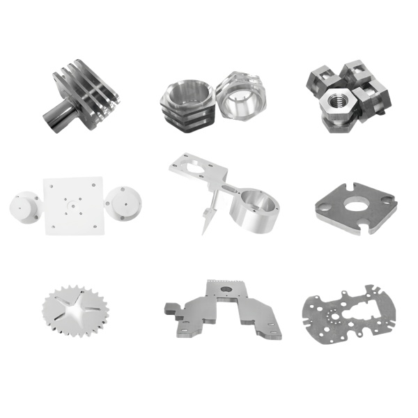
Clip spring force is determined by the bend radius, not by the material strength alone
A machined stainless steel clip—whether it is a retaining clip, a hose clamp spring, or an electrical grounding finger—derives its clamping force from the elastic bending of a cantilever or curved beam. The force is proportional to the material’s modulus of elasticity (roughly 200 GPa for austenitic stainless steel, regardless of heat treatment) and the moment of inertia of the cross-section, and inversely proportional to the cube of the beam length. What this means in practice: reducing the free length of a clip’s finger by 20 % increases its spring rate by roughly 95 % (1/0.8³ ≈ 1.95), while changing from 304 to 17-4 PH stainless steel (which has twice the yield strength) does not change the spring rate at all—it only raises the force at which the clip takes a permanent set.
We design clips with a minimum bend radius of 1.5× the material thickness at the root of the finger to avoid stress concentrations that initiate fatigue cracks. For 0.5 mm thick 304 stainless steel clips that must cycle more than 10,000 times (e.g., hose clamps on equipment that is disassembled for maintenance), we specify a root radius of 0.8–1.0 mm and verify it with a profile projector at 20× on the first article. Clips that fail before 10,000 cycles almost always show crack initiation at a sharp internal corner where the radius was below 0.5× thickness.
Washer flatness under the fastener head determines whether the preload is maintained
A machined washer may seem like the simplest component in any assembly—just a flat ring with a hole—but its flatness directly controls the bolt preload retention. When a washer is clamped between a bolt head and the mating surface, any gap between the washer face and the mating surface means that the bolt’s elastic stretch is partially absorbed by bending the washer closed rather than being transmitted as pure tension in the bolt shank. A washer with 0.05 mm of concave bow can reduce the effective bolt preload by 15–25 % compared to a perfectly flat washer at the same torque setting.
We machine washers with a facing operation that uses a light final pass (0.1 mm DOC) with a sharp insert, and we verify flatness on a granite surface plate with a 0.01 mm dial indicator. The spec is 0.02 mm TIR over the full face diameter for standard washers and 0.01 mm TIR for lock washers and conical seat washers where the contact area is smaller and the sensitivity to flatness error is higher. For washers thinner than 1 mm (where machining-induced warping is hard to avoid), we switch to a blanking-and-grinding process: blank the washer shape from strip stock, then grind both faces flat in a double-disc grinder that holds 0.005 mm parallelism automatically.
Small plate perpendicularity matters when the plate acts as a datum for adjacent assemblies
A machined plate that serves as a mounting bracket, a spacer, or an alignment reference carries geometric tolerances that are often under-specified on drawings. The most commonly overlooked one is perpendicularity between the mounting face and the edge or bore that locates an adjacent part. A perpendicularity error of 0.1 mm over a 20 mm projection height produces a positional error of 0.1 mm at the end of that projection—which may be half of the total positional tolerance budget for the assembled system.
We hold perpendicularity to 0.03 mm TIR per 10 mm of projection as a default for all plates that have a locating edge or bore, unless the drawing specifies otherwise. This is verified by placing the plate on a surface plate and running a height gauge along the feature in question; the total indicator reading over the full height must not exceed the specified TIR. Plates that exceed this limit are re-clamped and given a light trim pass (0.05 mm stock removal max) to correct the angle. The cost of this correction is about 30 seconds of machine time plus the CMM re-check—far cheaper than the assembly rework that would result from shipping an out-of-perpendicularity plate.
Burr direction on clipped edges affects both safety and function
The burr left on a sheared or machined edge of a small clip or plate is not just a cosmetic issue. On a retaining clip that slides into a groove during assembly, a burr on the leading edge increases the insertion force and can gouge the groove wall, creating debris that contaminates the assembly. On a washer that must sit flush against a surface, a burr on the outer diameter creates a point contact that prevents uniform clamping and can imprint the burr pattern into the softer mating surface (aluminum, plastic, or painted steel).
We specify burr direction on all critical edges as part of our internal process documentation: burrs must be directed toward the non-functional side of the part, or removed entirely if no non-functional side exists. The deburring method depends on the edge requirements:
- Standard: vibratory tumbling with abrasive ceramic media for 15–30 minutes. Removes burrs uniformly, produces a rounded edge (R0.05–R0.1 mm), and is suitable for bulk processing. Cost: approximately 0.01 USD per part in batch sizes above 100.
- Precision: thermal deburring (in an explosive deflashing chamber) or electrochemical deburring for parts where edge geometry must be preserved and only the burr removed. Used for sensor-housing clips and electrical contact springs where even 0.02 mm of edge rounding affects function.
- Critical: manual deburring with a hardened scraper under 10× magnification, followed by edge inspection. Reserved for aerospace and medical device applications where a missed burr could cause a safety-critical failure.
Material grain direction affects the fatigue life of cyclically loaded clips
When a clip or spring plate is blanked from strip stock (the most economical production method for thin stainless steel parts), the orientation of the blank relative to the rolling direction of the strip determines its fatigue performance in bending. Stainless steel strip has higher fatigue strength when loaded transverse to the rolling direction (across the grain) than when loaded parallel to it (along the grain), because the elongated grain structure provides more resistance to crack propagation across the grain boundaries.
We specify grain direction on all clip and spring drawings: the primary bending axis must be oriented perpendicular to the rolling direction. For parts blanked from 301 or 304 stainless steel strip in the full-hard condition (yield strength > 1100 MPa), following this rule improves bending fatigue life by a factor of 2–3× at the same stress amplitude. We verify compliance by marking the strip direction on the blank layout and inspecting the grain flow on a polished and etched cross-section of the first article. Parts that cannot be oriented correctly due to nesting constraints (material utilization would drop below 40 %) are redesigned to change the loading direction or are produced from bar stock instead of strip, accepting the higher material cost for the benefit of isotropic properties.
How we ensure dimensional consistency across a 10,000-piece clip order without measuring every part
For high-volume clip and washer orders, 100 % inspection is neither economical nor necessary if the process is capable. We use statistical process control (SPC) with subgroup size n=5, sampled every 30 minutes of production, to monitor critical dimensions (spring height, inside diameter, flatness). The control limits are set at ±3σ based on the initial 20 subgroups (100 parts), and the process is considered capable when Cpk > 1.33 for all critical characteristics.
When Cpk drops below 1.33—a signal that the process has drifted—we stop production, adjust the tool offset or replace the worn tool, and run five confirmation parts before resuming. This approach has kept our external defect rate (parts rejected by the customer) below 200 PPM across all clip and washer programs in the past 12 months. The key enabler is that our tooling is designed for quick adjustment: die heights are set via shims that can be changed in under 5 minutes, and punch diameters are monitored with a go/no-go ring gauge every 500 strokes so that wear is detected before it affects the part dimensions.
CNC Machining Parts is the range this part sits under; the overview page pulls together the tooling logic, finishing options and tolerance notes that apply across the family.
Specifications
| Item | Stainless Steel Small Machined Clips Washers and Plates |
|---|---|
| Brand | AUNOV |
| Designing | Send the drawing, or a plate sample we can measure, the quotation comes back with a manufacturability review attached. |
| Tooling | Tooling designed and cut in house, with your part number on the tool record. |
| Samples | Samples for approval come with a full dimensional report and material certification. |
| Materials | Stock for this part leads with 304 / 316 stainless steel, alongside carbon steel (SPCC / DC01), aluminium, brass and copper, with grade selection confirmed at drawing review. |
| Surface finish | The drawing requirement picks between zinc, nickel or chrome plating, e-coat, powder coat, anodising and passivation. |
| Processing | The draw sequence is staged, with in-line annealing wherever the draw ratio requires; piercing and CNC machining are done in house. |
| Equipment | Our press floor runs 5-250 T mechanical and 250-500 T hydraulic presses, in-house CNC cells and a temperature-controlled inspection room. |
| Tolerance | Tolerances to +/-0.1 mm as drawn, +/-0.03 mm after machining. |
| Delivery terms | Standard terms FOB, DDP offered to EU and US, T/T and L/C accepted, D/P for established customers, call-off schedules supported. |
Related Products


Request a Quote for This Part
Send a drawing or sketch — get material advice, tooling cost and a per-piece price within 24 hours (working days).