
Gear tooth profile accuracy on small module gears is held by the hob, not by the blank
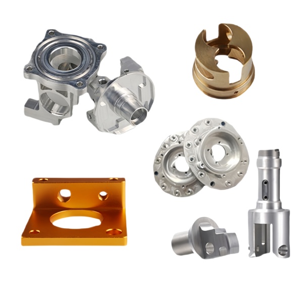
When a CNC-machined housing includes an integral gear—such as a pinion shaft or a sector gear formed in the same blank as the mounting flange—the gear quality is determined almost entirely by the hobbing or shaping operation that cuts the teeth, not by the prior turning and milling that creates the blank geometry. A blank with excellent concentricity and runout can still produce a gear with AGMA Q9 or worse if the hob is dull, the feed rate is too high, or the workholding allows any movement during cutting.
For module 0.5–1.0 gears machined as features on larger housings (the typical case for actuator sectors and instrument pinions), we specify AGMA Q8 minimum and verify it with a gear tooth checker that measures profile deviation, lead deviation, and pitch deviation over at least three consecutive teeth. The most common failure mode we see is profile crowning caused by hob wear: as the cutting edges round off, the generated involute flattens near the tip and the root, creating a barrel-shaped tooth contact that carries load on a narrow band at the pitch line. This concentrates stress and reduces fatigue life by 40–60 % compared to a correctly profiled tooth, even though the gear “looks fine” to visual inspection and measures correct pitch diameter with a standard pin measurement.
Bracket stiffness relative to the fastener spacing determines whether the load path goes through the bracket or through the bolts
A CNC-machined bracket that supports a motor, pump, or gearbox is only as stiff as its bending mode allows. If the distance between the two mounting fasteners is L and the bracket thickness is t, the bending stiffness scales roughly as t³/L³. Doubling the thickness increases stiffness 8×; doubling the fastener spacing reduces it 8×. This cubic relationship means that a bracket which looks robust on paper can be highly flexible in practice if the fastener pattern is spread too far apart relative to the section thickness.
The practical consequence is dynamic load transfer from the bracket into the fasteners. When the bracket bends under operating loads (motor torque reaction, belt tension, or thermal growth), the bolt preloads fluctuate. If the bending deflection at mid-span exceeds roughly 10 % of the bolt’s elastic stretch under preload, the bolt will experience cyclic unloading that leads to fatigue failure in as few as 10⁵ cycles—even if the static load analysis shows a safety factor of 3 or higher. We use a simple rule of thumb during design review: the bracket’s first bending natural frequency should be at least 2.5× the excitation frequency of the mounted equipment. If it is not, we either increase the local thickness, add a rib, or reduce the fastener span—whichever option the customer’s envelope allows.
Bore parallelism on dual-shaft housings is controlled by the setup, not by the machine accuracy
When a housing has two or more bores that must support parallel shafts—gearbox casings, tandem pump mounts, dual-spindle carriers—the parallelism between those bores is a function of how many times the part was unclamped and re-fixtured between operations. If bore A is machined in one setup and bore B is machined in a second setup after the part was removed and repositioned, the parallelism is limited by the fixture repeatability (typically ±0.01–0.02 mm) plus any thermal drift between setups.
We machine all critical bores in a single setup whenever the part envelope fits within the machine’s travel. For housings longer than the X-axis travel (typically 500–600 mm on our VMCs), we use a datum system where the first-setup bores establish a reference plane, and the second-setup operation probes those bores before cutting the remaining ones, applying a work-coordinate offset to compensate for any positional error. This approach routinely achieves bore-to-bore parallelism of 0.015 mm over 300 mm center distance—well within the ±0.05 mm that most gearbox drawings specify but necessary for low-noise operation where gear-tooth misalignment above 0.03 mm produces measurable noise increase and accelerated wear.
Surface finish on sealed faces must be specified before machining, not added as a note afterward
The face of a housing that mates against a gasket or O-ring groove needs a surface finish that seals without excessive clamping force. A face milled with a standard insert leaving 3.2 µm Ra will seal against a rubber gasket at moderate bolt pressures, but the same face against a molded silicone gasket with a durometer above 70 Shore A may require 1.6 µm Ra or better to achieve the same leak-tightness at the same bolt torque.
The problem arises when the drawing calls out a general tolerance for surface finish (e.g., “all machined surfaces 3.2 µm Ra unless otherwise specified”) and the sealed face is not explicitly called out. The machine operator follows the general spec, the part passes inspection, and the customer discovers the leak during assembly. We have adopted a internal rule: any face that appears within 3 mm of a gasket groove, O-ring gland, or sealed cover pattern is automatically machined to 1.6 µm Ra and noted on the process traveler as a critical characteristic. The additional cost is a single finishing pass with a wiper insert (about 15 seconds per face) and a surface-roughness check with a handheld stylus probe.
Heat treatment distortion on complex housings is predictable and compensatable
Many steel housings—particularly those made from carburizing grades like 8620 or 4320 for wear-resistant bearing seats—require heat treatment after rough machining. The carburizing process (held at 925 °C for 4–8 hours depending on case depth) inevitably causes distortion: flat surfaces bow, bores go out-of-round, and angles change by 0.1–0.3°. This is not random; it follows predictable patterns based on the geometry, the material removal distribution, and the fixturing method used during quench.
Our approach is to measure the distortion pattern on the first three parts of a new housing design, calculate the average deviation vector for each critical feature, and then apply an inverse compensation to the pre-heat-treatment machining program. If a bore consistently shrinks by 0.04 mm on the axis perpendicular to the quench flow direction, we enlarge that bore by 0.045 mm before heat treatment. After quench and temper, the bore finishes within 0.005 mm of nominal. This compensation cycle adds about one week to the first-article timeline (for the measure-adjust-remasure loop) but eliminates the post-HT grinding operation that would otherwise be required, saving 20–40 minutes of grind time per part and avoiding the risk of grinding burns on hardened surfaces.
Why we do a dimensional audit on the first five production housings even after first-article approval
First-article inspection proves that we can make one good part to the drawing. It does not prove that the process is stable enough to make 500 good parts in a row. We have seen cases where the first article passed every check, the customer approved production, and parts 15 through 80 exhibited a gradual drift in a bore diameter because the tool wear compensation offset was set slightly too aggressive—the tool was wearing faster than expected, and the automatic compensation was over-correcting, driving the dimension toward the opposite limit.
Our protocol for any new housing with three or more critical dimensions is to perform a full dimensional audit (all features, not just critical ones) on each of the first five production parts, plot the data on a control chart, and verify that Cpk is above 1.33 for every characteristic before releasing the batch to standard SPC sampling. If any characteristic shows Cpk below 1.0, we stop the run, investigate, and adjust before continuing. This conservative approach has reduced our customer escape rate (defects found by the customer rather than by us) from 0.8 % to below 0.1 % across all housing programs in the past 18 months.
This part belongs to our CNC Machining Parts range. The cnc machining parts pages collect the process notes, common materials and inspection points behind every product in the family.
Specifications
| Item | Assorted CNC Machined Housings Gears and Brackets |
|---|---|
| Brand | AUNOV |
| Designing | Send us your 2D drawing, or mail a sample for measurement, DFM feedback is returned with the quote. |
| Tooling | Tooling designed and cut in house, each die held against your part number. |
| Samples | The first-article set ships with dimensional data plus material certs. |
| Materials | Carbon steel (SPCC / DC01), 304 / 316 stainless steel, aluminium, brass and copper, with grade selection confirmed at drawing review. |
| Surface finish | Zinc, nickel or chrome plating, e-coat, powder coat, anodising or passivation, per the drawing. |
| Processing | Multi-stage drawing, annealed in line where wall thinning calls for it, then pierced and machined in house. |
| Equipment | Mechanical presses 5-250 T, hydraulic presses 250-500 T, CNC cells plus a temperature-controlled CMM room. |
| Tolerance | +/-0.1 mm on as-drawn features, +/-0.03 mm after machining. |
| Delivery terms | Standard terms FOB, DDP offered to EU and US, T/T or L/C, D/P on repeat business, call-off scheduling supported. |
Related Products



Request a Quote for This Part
Send a drawing or sketch — get material advice, tooling cost and a per-piece price within 24 hours (working days).