
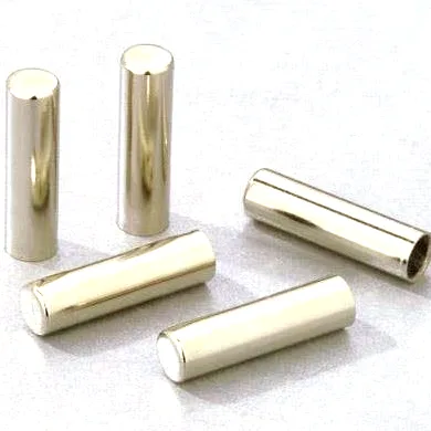
Where magnetism and a sliding fit meet: the solenoid valve tube
A solenoid valve tube – the sleeve a plunger moves inside, driven by a coil around it – is one of the more demanding deep-drawn stainless steel parts, because it must satisfy two requirements that pull in different directions. Electromagnetically, the tube must let the coil’s flux reach and move the plunger, which favours a thin wall and a magnetic material. Mechanically, it must guide the plunger smoothly and seal the fluid, which favours a robust wall and a corrosion-resistant, low-friction bore. A stainless steel deep drawn solenoid valve tube is the engineering that reconciles the two, and this page covers how.
The magnetic trade-off
Two families of solenoid design exist and the tube’s material follows. In a non-magnetic-sleeve design, the tube is a thin wall of austenitic stainless steel (typically 304 or 316) whose job is to let flux pass with minimal loss while resisting corrosion – thin walls and non-magnetic grades keep the magnetic path efficient. In a magnetic-pole design, the tube or parts of it are ferritic (400-series) to serve as a flux return, which improves actuation force but requires a bore finish that still allows the plunger to slide. Getting this wrong is a design error, not a manufacturing one: an austenitic tube specified where a ferritic is needed starves the solenoid of force, and a ferritic where corrosion dominates risks pitting. We ask for the coil’s design intent and the fluid’s aggressiveness at RFQ so the material and wall follow the actual requirement rather than a default grade.
The bore as a bearing surface
Inside the tube, the plunger slides – often millions of cycles in a solenoid valve, and it must do so without galling or sticking. That makes the bore a bearing surface, and its requirements are surface finish (low friction, defined roughness band), roundness (a plunger cannot slide freely in a slightly oval bore), straightness and cleanliness (any particle becomes a sticking point or a leak). Deep drawing forms the bore, and then sizing, ironing and sometimes a burnishing pass refine it to the sliding surface, with the exact sequence chosen for the grade and the finish. We hold the bore’s roundness and diameter to the plunger’s fit band, verify surface finish by roughness measurement, and recommend testing the finished bore with the customer’s own plunger in a cycling check, because sliding behaviour depends on the specific material pair, not the finish alone.
Sealing the fluid at the tube’s ends
A solenoid valve tube typically seals to its end fittings – a flange, a threaded boss, a brazed or welded joint depending on the valve design. Each sealing interface places requirements on the tube’s ends: a defined face or land that makes a reliable seal, thickness adequate for the joining process (thin tube ends are harder to weld or braze without distortion), and, for press-fit ends, a diameter held tightly. We form these end features in the same die sequence that produces the tube, keep them to a datum that shares the bore’s, and where the joining process is sensitive to tube-end geometry we ask for the joining specification early so the tube end is designed for it. A tube that seals perfectly and distorts at the weld has an end-design problem, and that is cheapest to fix before tooling.
Wall thickness: the thickness that makes the design work
Solenoid tube walls are thin by necessity – 0.3 mm to perhaps 1 mm – because wall thickness costs both magnetic efficiency and material. But a thin wall has to survive the drawing, the sizing and the joining without cracking, thinning excessively or losing roundness, and the closed end or shoulder must hold pressure. Our designs use generous radii where the shape allows, verify wall thickness at the critical sections on first articles, and choose the draw sequence (including anneal for austenitics) that keeps the wall’s thinning within the design’s allowance. The result is a tube that is thin where magnetism wants it thin and robust where sealing and joining need it robust – an optimization that lives entirely in the wall’s design and its forming, and that a buyer can only assess by the wall’s measured uniformity.
The coil and valve decide it, not the tube
The solenoid valve tube drawing with bore diameter, roundness and finish; wall thickness and the closed-end or shoulder geometry; the plunger’s fit dimensions; the coil’s design intent (magnetic or non-magnetic sleeve); the fluid’s nature for material selection; the end sealing and joining specs; the cleanliness and documentation level; and volume. We return a draw and finishing plan, a material recommendation, and a sample schedule – typically three to five weeks after die approval, with first articles carrying bore metrology, finish, wall thickness and the cleaning record, plus a plunger cycling check if the application warrants it.
Magnetic or non-magnetic sleeve – which does my valve need?
Magnetic or non-magnetic sleeve – how do I know which my valve needs?
It is set by the coil and valve design, not the tube. If you share the coil’s flux path intent, we will recommend the material and wall; getting this wrong is a design error that no manufacturing tolerance can fix, so it is worth settling before quoting.
Can you hold a plunger-fit bore in a thin wall?
Yes, with sizing and burnishing, and we hold the roundness the plunger’s sliding needs. If the wall is too thin for the fit band, we will say so – over-thin walls are a real limit.
Our valves stick after a while – is it the bore or contamination?
Both are possible: a bore finish that galls the plunger or particles lodged in the clearance. Send the tubes; our finish and cleanliness checks separate the causes, and the fix differs – a finishing change or a cleanliness process change.
Deep Drawn Tubes & Sleeves is the parent range for parts like this one; the overview page gathers the tooling logic, finishing options and tolerance notes that apply across the family.
Where this part is used
The sleeve a solenoid valve plunger runs inside is the part that has to be right in three directions at once: it guides the plunger through millions of strokes, it carries the fluid the valve is metering, and it sits inside a coil that decides whether the valve actuates at all. That third duty is why this is not simply a precision tube. A solenoid valve sleeve is usually the one component where the coil supplier, the valve designer and the tube maker have to agree on the material before anyone can quote it, because the grade decides whether the plunger moves at all.
In practice you will find this part in proportional and on-off valves for refrigeration, in hydraulic pilot valves, in medical fluid metering, and in fuel and emissions control. What is common to all of them is a small bore, a defined wall, and a fluid that must not be contaminated. The same tube also turns up where a coil is not involved but the geometry is: needle-valve bodies, orifice sleeves and sensor housings that carry a plunger. Where the coil is present, the sleeve is part of the magnetic circuit, and it gets specified alongside the coil rather than as a mechanical part.
What we need to quote it
To quote this properly we need the coil design intent – is the sleeve expected to be a non-magnetic path or a magnetic pole – and the fluid, because a refrigerant with oil, a hydraulic oil at 200 bar and a clean pharmaceutical-grade medium are three different corrosion problems. Give us the bore diameter and its tolerance, the wall thickness, the stroke length, and the pressure and temperature the sleeve sees, plus the number of plunger cycles expected in service. A sample sleeve with a measurement report is worth as much as a drawing here, because the bore’s finish and roundness are what the valve maker will actually measure.
Specifications
| Item | Stainless steel deep drawn solenoid valve tube |
|---|---|
| Brand | AUNOV |
| Designing | Made to your 2D/3D drawings (PDF, DWG, STEP, IGS) – a manufacturability review comes back with the quotation; the agreed version governs every later batch. |
| Tooling | Progressive and drawing dies are designed and built in house, so no tooling step is outsourced, and the charge is refundable against agreed volumes. |
| Samples | Sample parts are measured and reported before submission, so any deviation is corrected at sample stage, and the signed sample is kept for future reorders. |
| Materials | Standard stock: carbon steel (SPCC / DC01), 304 / 316 stainless steel, aluminium, brass; the final grade is fixed with the drawing review. |
| Surface finish | Surface treatment matched to the duty: plating, coating or polishing; masking and laser marking available where needed. |
| Processing | Precision tube drawing, cut to length and turned to the print; in-process checks sit between stages, not only at the end. |
| Equipment | Drawn-tube benches, in-line annealing and CNC turning; secondary ops run on CNC turning centres, inspection on the CMM. |
| Tolerance | +/-0.02 mm on fitted diameters, +/-0.1 mm on formed ends; GD&T per drawing, PPAP-style reports on request. |
| Delivery terms | FOB with DDP offered for EU and US addresses; payment T/T or L/C, freight quoted to destination. |
Related Products

Request a Quote for This Part
Send a drawing or sketch — get material advice, tooling cost and a per-piece price within 24 hours (working days).