
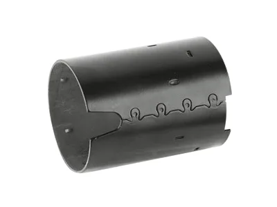
The starter frame: a datum platform carrying a whole mechanism
Every starter has one part that other parts locate from, and in many architectures that part is the auto starter motor frame. It carries the mounting interface to the engine, the pinion bore’s datum, the field’s axial position and often the drive-end register – which means the frame’s accuracy propagates into every functional dimension of the starter. Frames in this family are frequently compared against die-cast alternatives, and there is a real engineering case on both sides. This page covers the frame as a datum platform and where stamping wins.
Datum hierarchy and why stamping suits it
A starter frame’s primary datum is the mounting flange face – the face that seats to the bellhousing. Everything else derives from it: the pinion bore’s position, the field’s land, the drive-end register, any electrical mounting. Stamped frames achieve this hierarchy well because a drawn or formed frame produces the flange face and its datum features in one tooling sequence, so their relationship is set by the die and not by post-assembly. This contrasts with multi-piece assemblies, where each joint adds a tolerance and each fastener a settling point. The engineering outcome is a frame whose critical positions are consistent from part to part, which is what a starter’s pinion engagement and field alignment need.
Stamped frame versus die-cast
Aluminium or zinc die-cast frames bring thick sections, integrated bosses and shapes stamping cannot match, and for complex three-dimensional architectures they remain the right choice. Stamped steel frames win on the axes that matter to high-volume starter programmes: cost at volume (die-cast tooling is expensive, and per-part cost falls slower), weight (a well-designed stamped frame is competitive with cast aluminium at equal stiffness, and beats zinc), toughness (steel’s ductility tolerates handling and vibration that can crack castings), and magnetic function – a steel frame can carry field flux where a cast frame cannot, which in some architectures deletes a separate yoke. The honest comparison is per-programme: we quote stamped frames where their shape closes, and say so when a cast design is a better fit.
Carrying the mechanism’s loads
The frame transmits the same reaction loads as the starter’s body and housing – the multiplied cranking torque and the engagement thrust – to the engine mounting. Stamped frames answer with formed load paths from the pinion bore region to the mounting flange, generous radii where paths turn, and blank development that thickens sections only where load concentrates. A detail specific to frames: because other components mount to it, the frame must also stay flat and undistorted, so we control the flange’s flatness and the frame’s general stiffness together rather than accepting local deformation that a subsequent operation would have to correct. If a frame flexes under assembly clamping, its datums move and the whole starter inherits the error.
Detail features the frame owns
Frame features vary by architecture but often include the solenoid mount, the brush-holder or terminal lands, a drive-end register, and features that position the field axially. Each is die geometry, positioned to the same datum system. Our approach mirrors our other motor parts: in-strip forming and piercing, insert-based features so revisions happen at insert level, and first-article metrology that reports position relative to the flange datum the customer’s gauges use. Starter frames are also common candidates for the value-added steps we offer – bushing press-fit, field or brush-holder mounting – because doing them on the frame is doing them at the part where they can be gauged.
Formed ribs and a careful datum can match a casting
The frame drawing with the datum hierarchy identified (or a note inviting our review), the mounting flange dimensions, the pinion bore and its tolerance, the field architecture, the cranking reaction load if known, the under-hood corrosion spec, and volume. If the current design is die-cast, share it – we will say whether a stamped equivalent closes and what it would weigh and cost. First articles in four to five weeks after die approval.
Can a stamped frame match a die-cast frame’s stiffness?
Can a stamped frame match a die-cast frame’s stiffness?
Often, with formed ribs and a careful datum design – and where it cannot, we will show the numbers rather than claim equivalence. Steel’s higher modulus usually helps close the gap.
Our starter’s pinion engagement is inconsistent – is the frame the problem?
The frame sets engagement geometry, so a frame that flexes on clamping or moved its pinion bore is a prime suspect. Send frames and engagement data; the CMM comparison against print usually answers it.
Do you supply frames with the field or brush holder mounted?
On qualifying volumes, yes – mounted and gauged to your prints, which moves delicate alignment steps to the part level where they can be verified before assembly.
Automotive Motor Components is the parent range for parts like this one; the overview page gathers the tooling logic, finishing options and tolerance notes that apply across the family.
Specifications
| Item | Auto starter motor frame |
|---|---|
| Brand | AUNOV |
| Designing | Your drawing sets the part – DFM notes are returned before any tooling is cut; the agreed version governs every later batch. |
| Tooling | Progressive and drawing dies are designed and built in house, so tooling lead time stays under our control, and ownership is confirmed on the quotation. |
| Samples | Prototype and pre-production samples are provided against the drawing, so the sample is retained as the master, and production starts only after your written sign-off. |
| Materials | Carbon steel (SPCC / DC01), 304 / 316 stainless steel, aluminium, brass and copper – the grade is matched to the duty of this frame. |
| Surface finish | Phosphating gives coating adhesion; powder coating, e-coating or zinc plating follow, with chrome and nickel on visible faces. |
| Processing | Blanking, multi-stage deep drawing with interstage annealing, trimming and piercing, coining, then finishing. |
| Equipment | Mechanical capacity 5-250 T and hydraulic 250-500 T, with annealing ovens and CNC turning and machining centres alongside. |
| Tolerance | +/-0.1 mm to +/-0.2 mm general; critical features held to the drawing and verified on the first article. |
| Delivery terms | FOB, with DDP offered for EU and US addresses, payment by T/T or L/C, quoted in USD or EUR; price breaks tie to annual volume. |
Related Products


Request a Quote for This Part
Send a drawing or sketch — get material advice, tooling cost and a per-piece price within 24 hours (working days).