
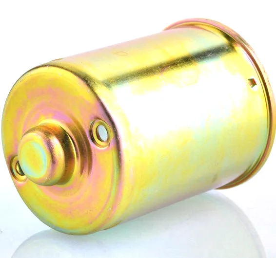
What the wiper motor body actually carries
Strip away the electrical function and a wiper motor body is a structural element in permanent tension: the worm drive at the output pushes back against the motor with a reaction torque, and that torque – cycling thousands of times per day, spiking when blades stall against ice – travels through the body to the vehicle structure. A body that handles the loads of a tidy lab test can still fail the real duty cycle, which is why wiper body engineering is fundamentally about fatigue and load paths, not just shape.
The load path, traced end to end
Follow a stall event through the part. Blades jam on ice; the motor’s electrical system holds torque near stall for a second or two; the worm tries to climb its wheel; the reaction – several newton-metres for a passenger-car wiper – arrives at the output bearing, passes through the body’s bearing seat, out through the mounting ears, and into the cowl bracketry. The body’s job is to carry that chain without relative movement at any joint, because movement is where wear lives: a bearing seat that flexes under load hammers its bushing; ears that deflect let the motor rock, and rock loosens bolts. Every reinforcement decision in a drawn body follows from this trace – stiffen the bearing seat, stiffen the ear roots, and leave the middle of the shell alone.
Where drawn bodies earn their stiffness
A drawn shell gets structural performance from geometry that costs nothing extra in the die. The flanged open end, bolted to the end-bell, forms a deep hat-section rim – the stiffest cheap shape in sheet metal. Local embosses under the ear roots spread the bolt clamping load over more wall. A body whose mounting ears are drawn integrally from the flange, rather than welded on, carries stall loads without the weld line acting as a crack starter. On our test rig, an integral-ear body survives 106 load cycles at 1.5x rated stall reaction with no crack initiation, while a comparable welded-ear design shows hairlines by mid-test. The drawing process is not just cheaper here – it is structurally better in the place that fails first.
Vibration endurance: the test that predicts the field
Wiper bodies rattle through a vehicle’s whole vibration diet – engine idle, road input, and their own torque pulsations. The endurance test that matters most combines a swept sinusoid (finding the body’s resonances with the motor mounted) with a long random-vibration soak at cowl-representative levels, checked periodically for fastener loosening and bushing migration. The drawn body’s contribution is predictable: consistent wall thickness means consistent resonance from part to part, so a motor maker who tunes a damper against sample number one still finds it working on unit number ten thousand. Welded or rolled constructions drift more across their population, and the drift shows up as “some units buzz” – the most tedious failure class in warranty statistics.
When the body needs more than forming gives
Three upgrades cover most heavy-duty cases. Thicker local stock – a thicker blank drawn so the bearing-seat region carries the extra wall while the shell stays light – is the first, and it is a blank-development trick rather than a redesign. A machined bearing carrier pressed into the drawn seat is the second, for motors whose spec demands spindle alignment beyond what forming holds. And a stress-relief choice is the third: for body geometries with sharp local forms, a low-temperature stress relief after drawing removes residual stress that would otherwise relax the ear positions over the first thermal cycles. We recommend each only when the load case asks for it – the base drawn body covers the passenger-car duty cycle with margin.
Almost always, and it is a geometry change
The body drawing, the rated stall reaction (or the motor’s torque curve and duty cycle), the mounting interface, and volume. If the application is commercial vehicle or marine, say so – the duty cycle doubles or triples and the reinforcement decisions change. First articles in three to four weeks after die approval, with the fatigue sample set quoted separately when the spec demands cycle testing before PPAP.
Current bodies crack at the ear root
Our current bodies crack at the ear root – is that fixable in the draw?
Almost always. Ear-root cracks mean the local radius is too sharp or the ear was welded; a redraw with a formed root radius and integral ears eliminates the class. Send a cracked sample – the fracture surface tells us whether it is fatigue (design) or overload (assembly).
Can you hold ear position under load without welding?
Yes – integral ears with embossed roots hold alignment through the rated load case. Welding adds stiffness but also adds distortion and a crack path; for wiper duty we consider integral forming the better engineering, not just the cheaper route.
Do you cycle-test bodies yourselves?
We run the rig on first articles and on defined audit samples for programmes that specify it; full qualification to a customer’s duty-cycle spec is quoted as a test line item, and the report ships with the PPAP file.
This part belongs to our Automotive Motor Components range. The automotive motor components pages collect the process notes, common materials and inspection points behind every product in the family.
Specifications
| Item | Wiper motor body |
|---|---|
| Brand | AUNOV |
| Designing | Driven by your drawing or a physical sample – DFM notes are returned before any tooling is cut; the approved drawing is kept as the controlled master. |
| Tooling | Tooling is built and held under your part number, so die cost stays transparent, and maintenance is tracked against the part number. |
| Samples | Samples are issued for approval before the run, so the part is proven before it is made in volume, and later batches are gauged back to the signed sample. |
| Materials | Carbon steel (SPCC / DC01), 304 / 316 stainless steel, aluminium, brass and copper – the grade is matched to the duty of this component. |
| Surface finish | Phosphating first for coating adhesion, then powder coating, e-coating or zinc plating; chrome and nickel are reserved for visible faces. |
| Processing | Parts are deep drawn from coil or blank with in-process annealing so the walls thin evenly, then trimmed, pierced, formed and finished. |
| Equipment | Presses from 5 to 250 T mechanical and 250-500 T hydraulic, annealing ovens on site, plus CNC turning and machining centres. |
| Tolerance | +/-0.03 mm on machined features, +/-0.1 mm on formed ones, with first-article inspection report. |
| Delivery terms | FOB, CIF or DDP per Incoterms 2020, payment by T/T or L/C, quoted in USD or EUR; each volume tier carries its own quoted price. |
Related Products


Request a Quote for This Part
Send a drawing or sketch — get material advice, tooling cost and a per-piece price within 24 hours (working days).