
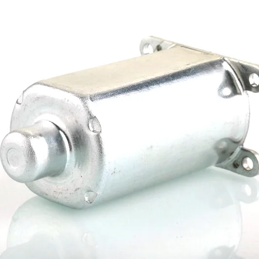
Bonded magnets and the drawn yoke that holds them
The power window regulator motor yoke works at the sharp end of small-motor magnetics: high torque density, tight air gaps, and ferrite or bonded magnets loaded close to saturation. But its defining problem is mechanical as much as magnetic – the magnets inside it must stay put through assembly shocks, anti-pinch reversals and a lifetime of thermal cycling, and the yoke is their structural home as well as their flux path. This page covers the yoke as a magnet container: surfaces, geometry, and the production details that keep the bond line honest.
The magnet land: a surface with two specifications
The yoke’s inner surface serves two masters. Magnetically, it sets the flux return’s geometry – its roundness controls air-gap uniformity, its thickness uniformity controls flux density distribution, as covered on our yoke and can pages. Adhesively, it is the substrate the magnets bond to, and adhesive specs read differently: a defined roughness band (typical 0.8-1.6 μm Ra for structural adhesive bonding), surface energy high enough to wet (dyne levels verified per lot), and freedom from drawing lubricant – the classic silent killer of magnet bonds. Meeting both specs on one drawn surface means the finishing stage is planned, not incidental: an aqueous wash after drawing, a surface-energy check before the parts ship, and a roughness gauge in the SPC set. Motor makers who trace “random magnet shift at endurance” to the yoke supplier’s oil film learn this the expensive way; our certificates carry the dyne result for exactly that reason.
Geometry that shares the load
A bonded magnet sees its worst loads at assembly drop and door-slam shock – impulses that try to shear the bond line. The yoke’s geometry can carry part of that load: shallow locating features formed into the magnet land (a keyway ridge, a positive stop) put shear loads into the steel instead of the adhesive; a slight wall land behind each magnet distributes the bond’s compression; and the magnet land’s width matches the magnet print with defined margins so the adhesive fillet forms consistently. None of these features shows on a magnetic drawing, and all of them belong there – the yoke is the magnet’s chassis, and chassis design is load-path thinking.
Drawn ring versus stamp-and-roll yoke
Yokes for this class arrive by two processes: a drawn ring (our route) or a flat stamp rolled and welded into a cylinder. The comparison is worth having explicitly. The drawn ring has no weld seam – no local stiffness anomaly, no weld bead inside the magnet land, no seam-corrosion site. Its roundness is inherited from the draw and restrike, typically holding 0.05 mm at the land. The rolled-weld yoke costs less tooling and suits very large diameters, but the seam must be ground before bonding, and its roundness after rolling usually needs a second sizing operation to match a drawn ring’s. For window regulator sizes – diameters under 50 mm – the drawn ring wins on consistency, and consistency is the currency of small-motor magnetics.
Thermal cycling: the bond’s real endurance test
The magnet-yoke joint endures more thermal cycles than anything else in the motor: -40 to +85°C door swings, with ferrite and steel expanding at different rates. The yoke’s contribution to survival is dimensional honesty – a magnet land that is round and uniform means the adhesive layer is uniform, and a uniform bond line survives cycling that a variable one cannot. Our validation for yoke programmes includes sectioned bond samples after thermal cycling on customer-specified schedules, because the claim “bonds survive the spec” belongs to a measurement, not a datasheet.
The yoke’s inner surface is the prime suspect
The yoke drawing with the magnet print (magnet dimensions, count, bonding spec including adhesive and surface-energy window), the motor’s flux requirements (magnet grade, pole count), and volume. First articles in three to four weeks after die approval, with bond-readiness certificates – roughness, dyne, cleanliness – included as standard for bonded-magnet programmes.
Magnets shift in endurance testing – is the yoke at fault?
Our magnets shift in endurance testing – is the yoke at fault?
It is the prime suspect, specifically its inner surface condition. Send shifted and unshifted samples; the surface analysis (roughness, residue) usually separates them within days.
Can you form the locating keyways for our magnets?
Yes – shallow formed features in the land are die geometry, and they move shear loads out of the adhesive. The magnet print is all we need.
Do you bond magnets as a service?
On qualifying volumes, yes – dedicated bonding jig, cure verification, pull-test sampling. The magnet and adhesive stay your specifications; the process and its verification become ours.
Automotive Motor Components is the parent range for parts like this one; the overview page gathers the tooling logic, finishing options and tolerance notes that apply across the family.
Specifications
| Item | Power window regulator motor yoke |
|---|---|
| Brand | AUNOV |
| Designing | Driven by your drawing or a physical sample – unusual walls, threads or tolerances are feasibility-checked first; changes are priced before they are made. |
| Tooling | Tooling is built and held under your part number, so no tooling step is outsourced, and ownership is confirmed on the quotation. |
| Samples | Samples are issued for approval before the run, so the approved first article becomes the gauge reference, and mass production is gated on that approval. |
| Materials | Carbon steel, 304 / 316 stainless steel, aluminium and brass are held in stock; the drawing review fixes the final grade. |
| Surface finish | Polishing, oxidising, zinc and nickel plating, powder coating, chrome plating and electrophoresis. |
| Processing | Blanking, multi-stage deep drawing with interstage annealing, trimming and piercing, coining, then finishing. |
| Equipment | Presses from 5 to 250 T mechanical and 250-500 T hydraulic, annealing ovens on site, plus CNC turning and machining centres. |
| Tolerance | +/-0.01 mm to +/-0.03 mm on controlled dimensions, with CMM reports and capability data for critical features. |
| Delivery terms | CIF or DDP, with FOB available, payment by T/T, L/C at sight or D/P; price breaks tie to annual volume. |
Related Products


Request a Quote for This Part
Send a drawing or sketch — get material advice, tooling cost and a per-piece price within 24 hours (working days).