

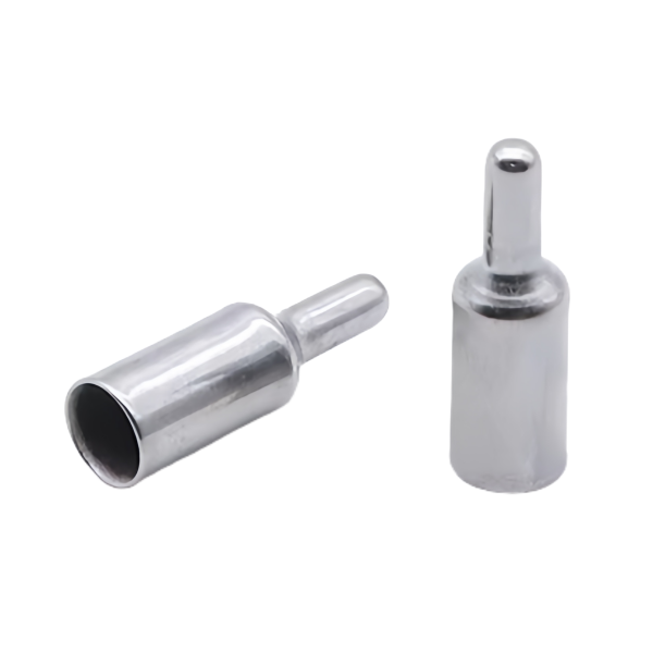
This is a three-piece assembly rather than a single formed part: a flanged tube, a closure, and the joint that makes them one pressure boundary. It is built that way because the geometry cannot be drawn as a single piece – the flange is too large relative to the tube, or the closed end is too deep, or the material at the two ends needs to be different.
Three pieces, because the shape will not come out of one die
Splitting the part is a route decision, not a compromise. A one-piece construction would need the whole assembly to be drawn from a single blank, which constrains how far the flange can stand off the tube and how thick the wall at the closed end can be. Making the tube and the closure separately and joining them lets each be made the way it wants to be made: the tube drawn for its bore and wall, the closure formed for its thickness, the flange machined for its face.
The joint becomes the feature to specify
Once a part is three pieces, the joint between them carries what a one-piece part would have carried in its wall. That means the joint preparation, the penetration and the condition afterwards are functional requirements rather than cosmetic ones, and they are inspected. A welded assembly in stainless steel also needs the weld to be made with a low-carbon or stabilised grade, or the heat of welding sensitises the metal beside it and the joint becomes the place corrosion starts.
The flange has to seal after welding, not before
This is the practical trap with a welded flanged assembly. Welding distorts, and a flange that was flat before the tube was welded to it is not necessarily flat afterwards – so if the gasket face is machined before welding, the weld can move it. Where the seal matters we finish the face after the assembly is welded, or we plan the sequence so the distortion is taken out, because a face that is flat in the wrong order is not a flat face.
The closed end is the pressure boundary
At the far end the closure holds the pressure, and because it is a separate piece it can be made to a thickness the forming of the tube would not have allowed. That is the advantage of the split: the tube can be drawn thin for its bore and the closure can be heavier where the pressure needs it, instead of the whole part being thickened to satisfy its worst point.
How the assembly is checked before it ships
The joint is inspected, the gasket face is verified flat after assembly, and the closure is checked to the requirement it carries.
First articles and retention samples are kept for the programme, so a reorder is assembled in the same sequence and finished in the same order. On a three-piece part whose flatness depends on when it was machined, that is what keeps the second batch sealing like the first.
This part belongs to our Deep Drawn Parts range, where the process notes and tolerance practice behind the whole family are collected.
Where this part is used
Three-piece flanged tube caps are built where a closed end has to seal against pressure and the flange is too large to draw in one piece. They turn up in pressure-containing sensor and probe assemblies, in hydraulic and pneumatic lines that need a flanged closed end, and in instrumentation tees and manifolds where a tube terminates at a flange face rather than a thread.
Stainless steel is the usual material because the joint is normally welded and the assembly then has to survive the process. The interesting requirement is not the tube or the cap on its own but the joint that makes them one pressure boundary.
What we need to quote it
Send the design pressure and the medium, the weld process used downstream, and the flange facing and gasket standard. Tell us whether the assembly is leak tested to your own specification, and if so in what units — we report pressure-decay and helium results against your spec rather than as a generic pass line. The three-piece construction should be stated on the drawing so the joint is treated as a feature.
Specifications
| Item | Stainless Steel Flanged Tube Caps, Three-Piece |
|---|---|
| Brand | AUNOV |
| Designing | Driven by your drawing or a physical sample – DFM notes are returned before any tooling is cut; the agreed version governs every later batch. |
| Tooling | Progressive and forming dies are designed, built and maintained on site. |
| Samples | Samples are issued for approval before the run, so the part is proven before it is made in volume, and mass production is gated on that approval. |
| Materials | Stock covers carbon steel (SPCC / DC01), 304 / 316 stainless steel, aluminium and brass; the final grade is fixed with the drawing review. |
| Surface finish | Finish per the drawing: plating, coating, anodising or passivation, plus masking and laser marking where needed. |
| Processing | Drawn-tube process with in-line annealing and finish turning; batch records are filed so a repeat order starts from approved data. |
| Equipment | Tube drawing benches with in-line annealing furnaces, with CNC turning centres for secondary operations and CMM inspection. |
| Tolerance | +/-0.02 mm on turned diameters, wall held to the agreed band; dimensional reports accompany the first article. |
| Delivery terms | FOB Ningbo or Shanghai, payment by T/T, L/C at sight or D/P; each volume tier carries its own quoted price. |
Related Products


Request a Quote for This Part
Send a drawing or sketch — get material advice, tooling cost and a per-piece price within 24 hours (working days).