
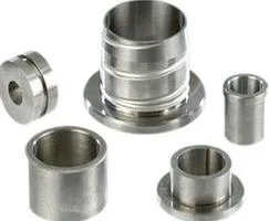
A compression union adapter is a small part with an unglamorous job and three separate interfaces, and its whole difficulty is that it has to convert between connection methods that do not naturally go together. It joins a compression fitting to something that is not a compression fitting – a thread, a flange, a tube, another material’s system. And every conversion it performs introduces a requirement that would not exist if the two sides were the same type.
So this part is really three specifications joined in one piece of metal, and the useful way to think about it is as a chain where each joint has to be right for the whole thing to work.
The three joints, and each one is independent
- The compression side. A compression fitting that bites a tube. Its requirements are the ferrule’s geometry, the body’s seat, the tube’s wall thickness range, and the assembly torque. These are covered in detail on the compression fitting page, and they apply here unchanged – with one extra factor that comes next.
- The thread side. A pipe thread or a tapered thread or a compression nut’s thread, sealing by interference or by a bonded seal or an O-ring. Its requirements are the familiar ones, and its seal method is what determines whether the connection tolerates a wide range of assembly torque.
- The transition itself. This is the joint that has no equivalent on a straight fitting: where the compression side’s bore meets the thread side’s bore. Three specific things happen here and they are all frequently missed.
The transition, which is the part’s actual design problem
- The bore change. The compression side’s bore and the thread side’s bore are almost never the same size, because a compression ferrule’s bore is smaller than the tube’s bore. So the adapter has a step inside it. That step is a restriction, a pressure drop, a turbulence generator, and – on a hygienic or a clean application – a place where a cleaning tool cannot go.
- Which side is bigger, and where the step is. If the thread side’s bore is smaller than the compression side’s, the adapter reduces the flow and the reduction is invisible in the part number. This is worth stating, because a customer who specifies a compression size and a thread size expects the fluid area to be roughly continuous, and where it is not, the pressure drop is higher than the assembly’s calculation assumes.
- The internal geometry at the step – whether it is a sharp shoulder, a cone, or a radius. A sharp shoulder inside an adapter is a debris trap and a turbulence generator, and in a vapour service it is a condensation trap. A small radius costs nothing.
Why adapters are usually a stock item, and where the temptation is
Adapters are available off the shelf in a wide range of combinations, and using a standard adapter is usually the right answer. The temptation to make a custom one is worth examining honestly, because there are three cases where it is justified and several where it is not.
- Justified: the sizes or standards are unusual and no standard item exists, or the existing standard items are all in a material that is not suitable.
- Justified: the adapter has to do something an off-the-shelf one cannot – a specific seal arrangement, a reduced bore for a flow requirement, a mounting feature, a length that has to clear something, or a material pairing for galvanic or thermal reasons.
- Justified: the adapter has to be integral with something else – a sensor boss, a bracket, a manifold block – so that there is no threaded joint and no leak path at all. This is where a custom adapter is genuinely valuable, because it removes two joints and replaces them with one continuous part.
- Not justified: the customer thinks a standard adapter is too expensive or too slow to obtain. This is the common case, and the honest answer is that a custom adapter will usually cost more, take longer, and have a worse tolerance story than a standard item, and it will usually be unnecessary.
Material, and this part has the galvanic question in a concentrated form
Carbon steel, 304 and 316 stainless steel, aluminium and brass, with grade and temper confirmed in writing before tooling. On a compression adapter the material decision has an extra dimension that the other parts on these pages do not, and it is worth stating clearly.
- An adapter is a junction between materials. This is the part’s defining characteristic. A compression fitting connects a fitting to a tube; a threaded fitting connects a fitting to a pipe. An adapter connects a fitting to a fitting, or a fitting to a pipe, and the two things it connects are frequently different materials – a stainless steel compression nut on a brass adapter, an aluminium body with a steel compression sleeve.
- Every dissimilar junction is a galvanic couple in a possibly wet connection. And the compression side is the wettest side. So the material pairing at the compression interface specifically deserves attention: a brass compression nut on a 316L adapter with a wet fluid is a couple at the wettest point on the assembly.
- The mitigation is a coating or a plating on one member of the pair, and on this part that means the adapter is often the coated member and the fitting is not. Where a stainless steel adapter is used, passivation is the relevant treatment; where a steel or brass adapter is used, a plating is often chosen both for corrosion and for galvanic isolation, and the plating’s thickness is a dimensional factor at the thread.
- 316L is the normal answer for a wetted adapter, on the chloride logic, and the L grade if there is welding.
- Where the two sides are in genuinely different temperature regimes – which is unusual on a small adapter but possible – the thermal expansion mismatch becomes a force on the joint, and the joint is the thread.
Each interface on an adapter carries its own kind of tolerance
+/-0.01 mm on machined faces and +/-0.05 mm on formed details, every stage logged against the part number. On a compression adapter the flagged dimensions are per interface, because each interface has its own tolerance and they are not the same kind of tolerance.
- The compression side’s ferrule seat and its geometry, to the compression fitting’s requirements – the same tolerances a compression fitting’s body needs.
- The thread side’s thread class and pitch diameter, gauged, and stated pre- or post-finish.
- Concentricity between the two sides, which is the adapter’s own requirement and which no single interface tolerance implies. An adapter whose compression side and thread side are not coaxial will not seat properly on either, and this is the tolerance that is unique to this part.
- The bore’s size on each side, and the step between them, as a positive statement rather than as two independent diameters.
- Sealing face’s flatness and perpendicularity, where there is a face seal.
- Length and the wrench flats as a fit to the wrench.
- General dimensions at a general band.
An adapter is only worth testing once both interfaces are proven
- Both interfaces tested – the compression side to a representative fitting and tube, and the thread side to a representative mating part – on a sample. On an adapter this is the only inspection that tests the whole part, because the part’s value is in the conversion and each conversion has to be tested separately.
- A functional leak test on the assembled combination, at the specified assembly torques.
- The compression side’s ferrule seating, verified against a standard – the same check as on a compression fitting.
- The thread side gauged, and the sealing face inspected.
- Concentricity between the two sides, measured on the CMM. On a small adapter this is a real measurement and it is the one that is most often omitted from an inspection plan because nobody has written it down.
- Finishing thickness and adhesion on the first article, with the masked threads and any masked ferrule seat verified – and where the plating is the galvanic isolation, its presence and thickness are functional requirements rather than decorative ones.
- Every stage logged against the part number, which on an adapter is worth doing because the part number often identifies a specific conversion of a specific standard item, and a repeat order needs to reproduce it exactly.
What is on the other side of the adapter
Why does this connection need an adapter at all – what is on the other side? Sometimes the answer is that two standard systems simply do not meet, and an adapter is the correct solution. But it is worth checking whether the design could be changed so that the connection does not need one, because removing an adapter removes an entire leak path. Three questions, and they sometimes have surprising answers. First: can the compression fitting’s mating half be specified to match the far side directly, instead of being connected through an adapter? A compression fitting’s nut will accept a standard tube or a standard thread, so in many cases the adapter is redundant and can be replaced by specifying the compression fitting’s own end type. Second: can the connection be made integral – the adapter’s job sometimes disappears if the assembly is machined as one part with no thread at all, which is both stronger and leak-free. And third: is the adapter there because of a size that does not exist in the standard system, or because of a material that is not right for the standard item? The answer determines whether this is a genuine custom part or an avoidable piece of complexity, and it is very much worth asking at enquiry rather than after the adapter has been designed.
This part sits inside our CNC Machining Parts range. Across the cnc machining parts pages you will find the process notes, common materials and inspection points behind every product in the family.
Specifications
| Item | Stainless Steel Sleeve Union Fittings, Five-Piece |
|---|---|
| Brand | AUNOV |
| Designing | The quotation follows your print, not a catalogue – unusual walls, threads or tolerances are checked for feasibility first. |
| Tooling | Progressive and drawing dies are designed and built in house, so tooling lead time stays under our control, and maintenance is tracked against the part number. |
| Samples | Samples are issued for approval before the run, and production starts only after written sign-off. |
| Materials | Carbon steel (SPCC / DC01), 304 / 316 stainless steel, aluminium and brass are held on site; grade and temper are confirmed in writing before tooling. |
| Surface finish | Surface treatment matched to the duty: plating, coating or polishing; alternatives quoted with the quotation, samples approved in writing. |
| Processing | CNC turning with milling and drilling in as few setups as the geometry allows; batch records are filed so a repeat order starts from approved data. |
| Equipment | Bar-fed CNC turning centres plus 3- and 4-axis machining centres; secondary ops run on CNC turning centres, inspection on the CMM. |
| Tolerance | +/-0.01 mm on machined faces, +/-0.05 mm on formed details; GD&T per drawing, PPAP-style reports on request. |
| Delivery terms | FOB, CIF or DDP per Incoterms 2020, payment by T/T, L/C at sight or D/P; each volume tier carries its own quoted price. |
Related Products


Request a Quote for This Part
Send a drawing or sketch — get material advice, tooling cost and a per-piece price within 24 hours (working days).