
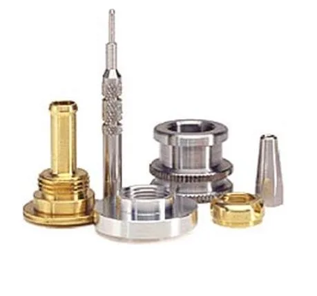
A valve body is a cavity with four or more openings, and the entire difficulty of the part is in the spaces between those openings. Inside a valve body, fluid turns corners, changes direction, and changes pressure – and the wall between one passage and the next is where the pressure boundary, the seal, the flow resistance and the tooling all compete for the same metal.
So a valve body is not a fitting and it is not a manifold. It is a pressure boundary with an internal geometry, and both of those things have requirements that a straight-through fitting does not have.
The seal is the part, and it decides the material
Every valve has one seat – sometimes more – and the seat’s geometry, its material, and its relationship to the moving element determine the valve’s function, its leakage class and its life. Four things about it are worth setting out precisely.
- The seat’s included angle and its diameter set the seating behaviour. On a metal-to-metal seat, a matched pair of cones seats reliably; an unmatched pair seats on its highest points and then leaks. The angle tolerance on a seat is therefore tighter than the general tolerance on the body, because it is not a size error that matters but a form error.
- The seat’s diameter sets the opening pressure or the cracking pressure. A larger seat area means more force is needed to open it. So the seat’s diameter is a functional dimension that ties the valve to its operating point, and the body has to hold it to a tolerance that keeps that operating point consistent.
- Seat hardness pairing. The hardest of the two mating faces wears first. Where a valve is intended to be a service item with a defined life, engineering the seat or the disc to be the sacrificial element – and choosing a hardened material for it – is a deliberate decision. Where the valve must hold without maintenance in a corrosive service, the pairing becomes a corrosion question instead.
- Where the seal is an elastomer, the requirements move: the seat becomes a gland and the gland’s geometry, its finish, and the elastomer’s compression all become the specification. An elastomer-seated valve can usually be made to leak far less than a metal-seated one at low differential pressure, but it has a temperature limit and it will not survive a dirty fluid.
Which of these applies should be settled before the body is designed, because it determines whether the body needs a hardenable material, whether it needs a corrosion-resistant one, and whether the seat’s dimensions are held to a tight band or a general one.
The internal passages, which nobody sees and everybody pays for
The internal geometry of a valve body decides its flow coefficient – how much pressure it drops at a given flow – and it is the reason two valve bodies with the same external dimensions and the same port sizes can behave very differently.
- Flow path length and shape. A body with sharp internal corners causes flow separation, which increases pressure drop and, in a liquid service, causes cavitation downstream of the corner. This is the same mechanism described on the cross-fitting page, and the same fix applies: generous internal radii.
- Multiple ports and the interference between them. This is the defining difficulty of a valve body and the reason it is harder than a fitting. When two ports’ passages meet, they remove metal from each other, they create a local thin section, and they create a low-pressure pocket at the intersection. All three are consequences of the same geometry.
- The thin section at an intersection. A port’s passage breaking into the main cavity leaves a ligament, and that ligament is the smallest section of the pressure boundary. It is where a pressure body will fail, and it is where a casting’s porosity or a machining’s residual stress will show up first.
- Drainability. A valve body will have a low point, and if the fluid is anything that solidifies or deposits, that low point matters. Whether the design should be drainable – and from where – is a question that is usually settled by the customer and almost never by the drawing.
Ports, threads, and the masking question
A valve body has several ports and each is a potential leak path and each has its own requirement.
- Tapped ports and the tap-drill’s effect. A port that will be connected to a fitting is threaded, and the port’s thread is a functional feature. Its class and its pitch diameter need stating per port.
- Plating a port changes the thread’s fit. On a valve body with four ports, this is four chances for the plating to interfere with a thread. The rule on the threaded ports is the same as elsewhere: mask them, or specify the dimensions post-plating with an allowance.
- A face-sealed port’s flatness and perpendicularity is a separate requirement from the port’s size, and on a valve body where a face seal carries the pressure, this is often the dimension that determines whether the valve leaks.
- Port positions and their relationship to the seat. The ports’ positions relative to the internal geometry determine the flow and therefore the valve’s behaviour, and their positions relative to the mounting faces determine whether the body will bolt up.
Material, and the two questions it answers
Carbon steel, 304 and 316 stainless steel, aluminium and brass, with grade and temper confirmed before tooling. On a valve body the material is answering two questions at once and it is worth keeping them separate.
- Corrosion, from the fluid and the environment. 304 for general service, 316L for anything chloride-bearing and for any welded condition. This is the same question as on the pump and valve bodies elsewhere in this section, and it is the one that most often gets answered by habit.
- Hardenability, from the seat and the wear requirement. If the body contains a metal-to-metal seat that has to be hardened, the body needs to be a hardenable steel. That is a completely different material requirement from corrosion resistance, and a corrosion-resistant austenitic stainless steel cannot be hardened. So a valve that needs both a hard seat and chloride resistance is a real engineering problem, and the usual answers are a 400-series martensitic stainless steel where corrosion is moderate, a hardened seat insert in a 316L body, or a weld-deposited seat.
- Aluminium is used where the fluid is benign and the weight matters, and it is a poor choice for a valve body’s general service for a specific reason: aluminium galls against the steel or brass fittings that a valve body inevitably connects to, and a seized valve body is a maintenance problem that a stainless steel body does not have.
- Brass is the traditional valve material for water and gas service and it is still correct for many applications. Its limitation is dezincification in acidic or saline water, and its behaviour under a metal-to-metal seat is good because it is a matched pair with itself.
Surface finish, and the two places it must be controlled
Natural, plated or coated per the print, with the agreed finish logged and samples approved in writing. On a valve body the finish has two critical applications and a general one.
- The seat’s surface, which is a sealing surface and where the finish directly affects the seat’s behaviour and its wear. A coarse finish on a seat will not seat; a plated seat will not seal consistently.
- The sealing faces, where a gasket or an O-ring lands. Plating changes both the size and the texture and both matter for a seal.
- The internal passages. Here it is worth being specific: on a valve body the internal surface roughness affects both the flow coefficient and, in a liquid service, where the boundary layer separates and whether cavitation begins. A polished internal passage in a cavitating service is a real and often-expensive improvement. The internal finish is not cosmetic on this part.
- Everything else – the external surfaces, where the finish is corrosion protection and appearance.
Which means the masking list on a valve body is unusually long: threads, seal faces, the seat, any internal passage that needs a defined finish, the mounting faces, and any datum. Naming them by location is the way to get it right.
Tolerance, allocated to the seat and the ports
+/-0.01 mm on critical bores, confirmed at the DFM stage, dimensional reports accompanying the first article. On a valve body the flagged dimensions are specific.
- The seat’s included angle, its diameter, and its concentricity to the body, as a group. These three together define the valve’s seating behaviour and its operating point, and a body that is correct in all three individually and wrong in their relationship will not seal consistently.
- The seat’s position along the body’s axis, which sets how much travel the moving element has and therefore the valve’s opening characteristic.
- Each port’s thread, gauged, every port.
- Each port’s face flatness and perpendicularity, where face-sealed.
- Concentricity of the internal passages to the body’s external mounting features, where the internal geometry has to line up with something outside.
- Flatness of the mounting faces and the position of the port pattern to them.
- The internal passages’ sizes and, where it matters, their surface finish, stated as a flow-relevant characteristic rather than as a general note.
- General features at a general band. On a valve body there is often room to recover tolerance cost on the outside because the outside does not do much.
On a pressure boundary the leak test is the only inspection that counts
- A functional leak or pressure test on the finished body, ideally with a seat fitted, and preferably on every part. On a pressure boundary this is the only inspection that tests the specification, and it is the single highest-value item on this page.
- A seat-fit check, confirming the body will accept and seat the intended closure element, on a sample or on every part where the seat is critical.
- The seat’s angle and concentricity measured on the CMM, as a group with the position.
- Each port’s thread gauged and each port’s face inspected.
- Internal passages inspected for burrs, tool witness and internal radii – this is a visual and tactile inspection and it needs an agreed standard, and on a cast or machined body it is the item that most often gets skipped.
- Dimensional report on the flagged dimensions accompanying the first article, with the material certification and the finish condition recorded.
- In-process checks between stages rather than only at the end, which on a multi-operation body is what catches a boring operation that has started to drift before it has produced a batch of bodies that will not seal.
Whether the valve will ever be opened
Is this valve meant to be serviced, and how often? That question determines more about this part than anything else on the drawing. A valve intended to be serviced has replaceable seats and wear parts, which means the seat must be a separately identified material with a defined hardness, which means the body’s material must be chosen so that the seat can be hardened or replaced – and that in turn constrains the body’s grade. A valve intended as a non-service item in a fixed installation can be a single piece in one material with a metal-to-metal seat and no replaceability, which is cheaper and entirely adequate. And a valve in a corrosive service that also has to hold tight needs both corrosion resistance and a hardenable seat, which is a genuinely hard requirement and one that is usually discovered late. Asking whether the valve will ever be opened costs one sentence and it settles the material, the seat’s specification, the number of parts in the assembly, and the maintenance documentation.
CNC Machining Parts is the range this part sits under; the overview page pulls together the tooling logic, finishing options and tolerance notes that apply across the family.
Specifications
| Item | Stainless Steel Machined Valve Bodies and Posts |
|---|---|
| Brand | AUNOV |
| Designing | Send drawings, or send a sample to be measured – DFM notes are returned before any tooling is cut; the same drawing is used for every repeat order. |
| Tooling | Dies, fixtures and gauges are made in our own toolroom, so no tooling step is outsourced, and the charge is refundable against agreed volumes. |
| Samples | Prototype and pre-production samples are provided against the drawing, so the sample is retained as the master, and mass production is gated on that approval. |
| Materials | Stock covers carbon steel (SPCC / DC01), 304 / 316 stainless steel, aluminium and brass; grade and temper are confirmed in writing before tooling. |
| Surface finish | Natural, plated or coated – the print decides, and the agreed finish is logged; alternatives quoted with the quotation, samples approved in writing. |
| Processing | CNC turning with milling and drilling in as few setups as the geometry allows; in-process checks sit between stages, not only at the end. |
| Equipment | Turning centres fed from bar, with machining centres for milled features, with in-house toolmaking to keep dies and fixtures maintained. |
| Tolerance | +/-0.01 mm on critical bores, confirms at DFM stage; dimensional reports accompany the first article. |
| Delivery terms | FOB Ningbo or Shanghai, payment by T/T, L/C at sight or D/P; repeat orders reuse the approved first article. |
Related Products


Request a Quote for This Part
Send a drawing or sketch — get material advice, tooling cost and a per-piece price within 24 hours (working days).