
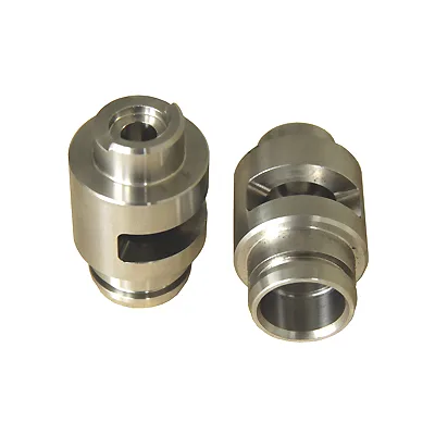
A two-piece quick-connect coupling is one of the few parts where the failure mode is not “it broke” but “it released when it shouldn’t have” or “it would not release when it should”. Everything about its design is a valve: a controlled gap that opens on demand, a controlled interference that closes under load, and a deliberate leak path for the trapped pressure that has to go somewhere when it opens.
Which means the interesting dimensions on this part are not the diameters. They are the flow paths, the release mechanism’s geometry, and one small feature – the vent – that is almost never on the drawing and that decides whether the coupling can be used at all.
Why it is two pieces, and what each piece is for
A quick coupling is a socket and a plug. Separating them is usually done by pulling, which means the coupling has to hold pressure and resist pull-out while also permitting a deliberate disconnect. That is a contradictory pair of requirements and the design resolves it by splitting it between the two halves.
- The socket is the female half and it carries the housing side of the connection. It has the body bore, the seal, and the part that the plug’s valve stem enters.
- The plug is the male half and it carries the valve. When the two are pushed together, the plug’s nose compresses the seal and opens the plug’s own valve. When the two are pulled apart, the seal stops the flow and the plug’s valve closes on its own seat.
The functional consequence of the two-piece arrangement is that the seal has to work in both states – sealed against pressure while disconnected, and sealed against pressure while connected but with the flow path opened. A coupling that seals well when connected but weeps when disconnected is a common and specific failure, and it is a seal design problem rather than a tolerance problem.
The vent, which is the feature nobody draws
When a connected coupling is disconnected, the fluid trapped in the cavity between the two valves has nowhere to go. If the coupling has no vent, that fluid has to go somewhere it should not, and the practical results are one or more of: the coupling resists release because of hydraulic lock, the escaping fluid is ejected into the surroundings, or the valve is damaged by the pressure spike as it closes.
So a working quick coupling needs a deliberate path for that fluid, and there are three places it can be:
- A vent through the plug’s valve stem, which bleeds the cavity back through the flow path as the coupling separates. This is the most common arrangement and it means the valve stem is a small drilled passage rather than a solid rod.
- A vent through the socket’s body, which is less common because it puts a hole in a pressure boundary that has to be sealed around the coupling’s mounting face.
- A deliberate leak at the seal, which is a last-resort arrangement and a poor one, because a coupling designed to leak at the seal will lose fluid continuously while connected.
The vent’s dimension is a real specification with a real range. Too small and it restricts the release rate; too large and it is a permanent leak path; and on a coupling with a high flow rate the vent’s restriction can affect how quickly pressure equalises, which affects the cavitation behaviour on disconnect. The drawing needs to show the vent’s existence, its path and its size. A coupling with no specified vent will be built without one, and it will either not release or will leak.
The valve, and its seat
The valve is the part that decides whether the coupling is reliable, and it has three requirements that are in tension.
- It must seal. That means a seat – on the plug’s nose, usually a small flat or an annular face – that is flat, clean, and made of a material that will take the repeated sealing contact.
- It must open with a reasonable force. The spring force that pushes the valve onto its seat is what the user overcomes when connecting, and it also sets how strongly the coupling resists a pressure-driven pop-off. This is a design decision, not a result.
- It must not damage anything when it closes. A valve that slams shut on disconnection takes an impact, and in brass the impact produces a raised lip around the seat. That lip is the classic cause of a coupling that leaks after a few hundred cycles, and it is why the seat’s geometry and the closing rate matter as much as the spring.
Three design choices that help, and all of them should be visible on the drawing or in the specification:
- A defined closing rate, usually achieved with a small pilot or a controlled spring, so the valve does not slam.
- A hardened or plated seat where the valve closes onto the body, so the wear is taken by a hard pair rather than by two brass faces.
- A defined seat geometry – flat, spherical, or conical – with a tolerance and a finish, because the seat is the sealing surface and it is treated as one.
The seal, which is what actually stops the fluid
On most quick couplings the seal is an elastomeric O-ring or a proprietary profile seated in a groove, and it is the item that determines the coupling’s leak rate. Three things about it belong on the drawing.
- Material compatibility, stated. The fluid, the temperature and the elastomer have to agree. A coupling rated for water at ambient is not necessarily right for a hydrocarbon at 120 degrees, and this is not a fitting that can be changed at the assembly line.
- Gland fill, and what over-compression does. A seal that is compressed too far extrudes into the clearance gap between the plug and the socket and fails there – a failure that looks like a leak along the plug rather than at the seal. Gland fill should be specified as a percentage, and the groove’s geometry follows from it.
- The groove’s finish and position. A sealing groove’s surface finish affects the seal’s seating, and the groove’s position relative to the coupling’s face determines how much compression the seal sees at the coupling’s assembled length.
Release, and how the user is meant to operate it
Many quick couplings are intended to be disconnected without tools, which is a real requirement with real consequences.
- The release mechanism’s geometry – a sleeve, a collar, a ring, a lever – determines the axial force the user must apply to overcome the seal’s friction and the spring. On a small coupling this is the part that determines whether the coupling is usable, and its geometry is usually treated as an appearance decision.
- The sleeve’s travel has to be sufficient to open the valve before the parts separate, and there is a specific relationship between the sleeve’s travel, the valve’s travel and the seal’s release that is easy to get wrong.
- If the coupling is not tool-free, then it should not be designed as though it is. A coupling that requires pliers to release and is marketed as a quick connect will generate returns.
And one point about use that belongs in the specification rather than in a manual: whether the coupling may be connected while depressurised only, or whether it may be connected under pressure. Many quick couplings are not designed for pressurised connection, and on a pressure connection that is a safety-relevant statement rather than a usability one.
Brass machines to fine detail, which is what a coupling socket needs
H62 and H65 brass at 0.8 to 4.0 mm, chosen for conductivity, fine detail and corrosion resistance. On this part the brass choice is well founded and the specific consequences are worth stating.
- Brass machines to fine detail, which is what a coupling’s small internal passages and its valve seat require.
- Brass is ductile, which is good for a seal that has to conform and for a seat that has to take a small deformation, and it is why a brass coupling’s threads and its press-fit sections tolerate small variation.
- Brass’s weakness on this part is dezincification, and it is a real concern in exactly the applications a quick coupling tends to see – water systems, some industrial fluids, some environments. H65’s lower zinc content is the mitigation, and where the environment is genuinely chloride-bearing or acidic, a different material should be considered.
- Conductivity is a genuine reason to specify brass on a coupling that is used as an electrical bonding path – which happens in fuel systems and in some instrumentation. If that is the reason, the drawing should say so and the requirement should be testable.
Finish – natural, plated or coated, with masking and laser marking. On a coupling the finish decisions are narrow and specific: the seal groove must be left clean and unmasked, the valve’s seat region must not be coated in a way that changes its geometry, and the release mechanism’s outer surfaces are where a plating serves a purpose because they are handled.
Allocate by function: the valve’s seat and travel go first
+/-0.01 mm on ground diameters, GD&T from the print, capability checked on the first article. On this part the allocation is worth stating by function rather than by size.
- The valve’s seat and the valve’s travel, held tightly. The seat’s flatness and position and the valve’s travel distance together set the coupling’s internal volume and therefore its leak-on-disconnect behaviour.
- The vent’s path and its size, held – this is a functional dimension, not a detail.
- Concentricity of the plug’s valve to the socket’s bore, because the seal’s compression varies around the circumference if the axes are not aligned and a misaligned valve will seat unevenly.
- The seal groove’s dimensions – width, depth, and position to the mating face – to the gland fill’s requirement.
- The mating face’s flatness and perpendicularity, because that face is both the mounting datum and, on many designs, part of the sealing path.
- The release sleeve’s travel, as a measured functional characteristic rather than a general length.
Inspection in practice: the valve and seat on every part, functionally – the seal against pressure and the release under load – rather than only dimensionally; the vent’s function verified by confirming that the coupling releases without residual pressure locking; the seal groove’s dimensions on every part; the release force measured on a sample; and a first article cycled through a stated number of connect-disconnect operations and re-inspected, which is the only way to find out whether the seat is developing the lip that causes the classic late-life leak.
Connected or disconnected under pressure, and by hand
Is this coupling ever connected or disconnected under pressure, and is it intended to be operated by hand without tools? Those two questions decide the valve’s design, the release mechanism’s geometry, whether a vent is mandatory, and whether the seal can be an elastomer or has to be a metal-to-metal seal. They also decide the safety documentation the part needs. A coupling for a low-pressure instrument line, operated by hand, on a depressurised system, is a relatively forgiving part. A coupling on a fuel or hydraulic line that will be connected live and disconnected by a technician in the field is a different component entirely, with a different seat geometry, a different spring rate, a positive-lock requirement, and a much heavier qualification burden. Saying which of the two it is at enquiry stage costs two sentences and it changes the part, the price, the lead time and the paperwork.
This part belongs to our CNC Machining Parts range. The cnc machining parts pages collect the process notes, common materials and inspection points behind every product in the family.
Specifications
| Item | Brass Quick-Connect Coupling Sockets, Two-Piece |
|---|---|
| Brand | AUNOV |
| Designing | Your drawing sets the part – DFM notes are returned before any tooling is cut; revisions are re-quoted once rather than silently absorbed. |
| Tooling | Dies, fixtures and gauges are made in our own toolroom, so the die charge appears as its own quotation line, and maintenance is tracked against the part number. |
| Samples | Pre-production samples come with a full inspection report, so the part is proven before it is made in volume, and later batches are gauged back to the signed sample. |
| Materials | H62 / H65 brass, 0.8-4.0 mm, selected for conductivity, fine surface detail and corrosion resistance on this fitting. |
| Surface finish | Natural, plated or coated – the print decides, and the agreed finish is logged; masking and laser marking available where needed. |
| Processing | Turn-mill machining, critical diameters finished in one setup; every stage is logged against your part number. |
| Equipment | 12 CNC turning centres with automatic bar feeders; first articles and batch samples are checked on the CMM. |
| Tolerance | +/-0.01 mm on ground diameters, with GD&T taken from your print; capability is checked on the first article before the run continues. |
| Delivery terms | FOB Ningbo or Shanghai, T/T or L/C, with D/P accepted on repeat business; sea or air freight is quoted to your door. |
Related Products


Request a Quote for This Part
Send a drawing or sketch — get material advice, tooling cost and a per-piece price within 24 hours (working days).