
An L-corner bracket is two brackets, and it fails at their intersection
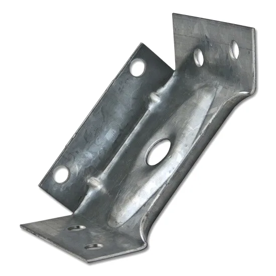
A galvanized steel L-corner mounting bracket is two mounting brackets welded or formed into a 90-degree corner. That sounds trivial and it is one of the more structurally awkward shapes in this family, because a corner is a stress concentration and an L-bracket has the properties of both of its legs while getting the worst of neither. Understanding why requires looking at what happens when a load path has to turn a corner – which is precisely what this part asks the material to do.
We stamp and form this in a progressive die with minimal secondary work, on 5-250 T presses running progressive and compound dies, backed by CNC turning centres and a climate-controlled inspection room. Batch records are filed so a repeat order starts from approved data. Tolerance runs +/-0.05 mm to +/-0.1 mm across the part, with critical dimensions carrying CMM data with the shipment. The material here is brass H62 or H65 in strip or bar at 0.8-4.0 mm nominal – the grade picked for machinability and plating adhesion – with surface treatment matched to the duty and the finish inspected alongside the dimensional report on the first article. This page is about corner stress, the two-leg load path, and why an L is not simply two brackets.
A load that turns a corner
Think about a load applied to one leg of the L, in the plane of the bracket, directed along that leg’s axis. To reach the mounting face on the other leg, that load has to turn 90 degrees. The material at the corner has to carry the load in two directions at once, and the corner region is where both directions’ stress fields overlap. The result is a stress concentration at the corner whose severity depends on the corner’s geometry:
- A sharp internal corner is a severe stress raiser. The stress at a sharp internal corner can be several times the nominal stress in the adjacent material. Under static load this may be acceptable; under cyclic load it is a crack initiator.
- A generous internal radius reduces it substantially. This is the single most effective design change on this part type and it costs nothing – it just requires the corner radius to be specified.
- The corner’s section depth matters. A bracket whose corner is formed from a flat sheet has very little material at the corner compared to a cast or machined corner, so the stress concentration is working on a small section. Adding a formed gusset or a bead at the corner puts material exactly where the stress is highest, which is far more effective than adding thickness uniformly.
The two legs have different jobs, and they need different thicknesses
A common error on L-brackets is specifying one thickness for the whole part. It is almost never right, because the two legs are doing different work:
- The mounting leg lies flat against a surface and takes the bolt load directly into that surface. It needs adequate bearing area around the holes and adequate flatness so the bolts do not have to pull it into contact. It does not need much section depth.
- The standing leg carries the off-plane load – the load trying to peel the bracket away from its mounting surface. This is the harder case, because peeling load is resisted by the bracket’s bending stiffness at its root, and a sheet-metal bracket resists it by flexing at the bend rather than by failing. That is often acceptable, and where it is not, the bracket needs a gusset.
- The corner takes the combination. It is where a peeling load from the standing leg transfers into the mounting leg, and it is the most highly stressed region on the part.
So: the standing leg needs section depth, the mounting leg needs bearing area and flatness, and the corner needs either a generous radius or more material. Three different requirements, and one thickness will not satisfy all of them.
Peel load and the reason gussets exist
The peeling case is worth separating out because it is where L-brackets actually fail in service, and it behaves unlike the intuitive picture:
- A peel load does not break the fastener; it peels the bracket. The bracket’s root at the bend flexes, and the failure is a tear starting at the edge of the mounting leg and running toward the nearest hole. This is the classic failure mode of an unstiffened angle bracket, and it is predictable.
- The tear runs to the nearest hole. Which means hole position is a fatigue and strength variable, not just a mounting detail. A hole close to the bend edge makes the tear shorter and more likely; a generous edge distance makes the bracket substantially stronger.
- A gusset solves it cheaply. A formed gusset – a triangular piece of material folded up from the mounting leg into the standing leg – puts material exactly at the corner and dramatically increases the peel capacity. It is one extra forming operation and it is almost always the right answer.
- A formed bead at the bend is the alternative, where a gusset would interfere with what the bracket has to clear. A bead stiffens the bend section without adding bulk.
Flatness, and the bolt-load requirement
The mounting leg’s flatness is functional, not cosmetic. If the leg is dished, the bolts pull it into contact and the clamping is uneven, which produces two problems:
- Uneven preload. One bolt carries most of the load and the others carry little, so the joint’s slip resistance is governed by the worst bolt rather than the average.
- The bracket can rock. And a rocking bracket under cyclic load produces fretting at the interface, which wears both the bracket and its mounting surface.
The fix is the same as on any stamped bracket: specify flatness against a named surface, and where the part is going to be visible or where the flatness matters, coin the leg. A bracket formed from 0.8-4.0 mm brass will not be flat by itself.
Brass, and why it is specified for this part
Brass H62 or H65 in strip or bar at 0.8-4.0 mm nominal – the grade picked for machinability and plating adhesion. Both of those reasons matter on this part:
- Machinability. H62 and H65 machine well, and on an L-bracket any secondary feature – a tapped hole, a chamfer, a machined pad – is turned rather than ground. H65’s free-cutting behaviour matters where there is meaningful machining.
- Plating adhesion. This is the more specific reason. Brass plates well and holds plating better than many substrates, and where a bracket needs a corrosion-resistant or decorative plating, brass is a reliable base for it. Zinc plating on brass is a standard and durable combination.
- Formability. Brass stamps and forms well into tight corner radii without cracking, which is valuable on a part whose corner radius is its most important feature.
- Corrosion resistance. Brass is stable in ordinary atmospheres and in many mild environments – though it dezincifies in acidic or ammonia-bearing conditions, so the medium matters.
- The lead question, again. H65’s lead content has to be checked against the application, and lead-free options are available.
Galvanizing and the dimensional question
Surface treatment matched to the duty, with the finish inspected alongside the dimensional report on the first article. On a bracket described as galvanized, four points:
- Growth changes the leg positions. Plating adds material to every surface, so the angle between the two legs is slightly affected and the leg lengths grow at their ends. Where a leg has to fit inside another part’s clearance, this closes the gap.
- Hole sizes shrink by roughly twice the plating thickness. On a leg with mounting holes this is usually harmless; on a locating hole it is a fit change.
- The corner radius is where the coating is thinnest, because the outer corner’s surface area per unit of projection is highest. So the corner – the most highly stressed region on the part – is also where the protective coating is weakest. That is a real and specific concern on this part type.
- Hot-dip versus electroplated. Hot-dip galvanising gives a much thicker, less uniform coating and is generally unsuitable on a bracket with fitted dimensions; zinc electroplating is the usual answer for a part described as galvanized. The drawing should distinguish them.
Drawing this bracket right
Seven things worth settling, and the first three are the ones that change whether the part works:
- The internal corner radius, stated as a dimension. This is the single most effective design parameter on this part and it is almost always left to the toolmaker.
- Whether a gusset or a bead is required, and its geometry if so. If the bracket sees peel load and has no gusset, that should be a conscious decision.
- Thickness of each leg separately, where they differ.
- Flatness of the mounting leg, against a named surface.
- Edge distances from the bend to the first hole, because that governs the tear resistance.
- Whether dimensions apply before or after plating, on anything the coating changes.
- The peel load the bracket must carry, or a statement that the load is in-plane only. This determines whether the corner needs to be designed at all, and it is the question most often left unanswered.
And the design question worth raising: does this need to be an L at all, or would two separate flat brackets with separate fixings do the same job. An L-bracket’s advantage is that it fixes two surfaces with one part and one fastener set. Where that convenience is not needed – where the two surfaces could be fixed independently – two flat brackets are simpler, flatter, cheaper to tool, and each can be stiffened independently in the way that its load actually requires. It is worth confirming that the corner is doing something necessary before paying to design around it.
This part belongs to our Custom Metal Stamping Parts range. The custom metal stamping parts pages collect the process notes, common materials and inspection points behind every product in the family.
Specifications
| Item | Galvanized Steel L-Corner Mounting Bracket |
|---|---|
| Brand | AUNOV |
| Designing | Your drawing sets the part – unusual walls, threads or tolerances are feasibility-checked first; the approved drawing is kept as the controlled master. |
| Tooling | Die design and toolmaking stay in house, so the die charge appears as its own quotation line, and ownership is confirmed on the quotation. |
| Samples | Sample parts are measured and reported before submission, so the approved first article becomes the gauge reference, and production starts only after your written sign-off. |
| Materials | Brass H62 / H65 in strip or bar, 0.8-4.0 mm nominal – the grade picked for machinability and plating adhesion. |
| Surface finish | Surface treatment matched to the duty: plating, coating or polishing; the finish is inspected with the dimensional report on the first article. |
| Processing | Stamping and forming in a progressive die with minimal secondary work; batch records are filed so a repeat order starts from approved data. |
| Equipment | 5-250 T presses running progressive and compound dies, backed by CNC turning centres and a climate-controlled inspection room. |
| Tolerance | +/-0.05 mm to +/-0.1 mm across the part; critical dimensions carry CMM data with the shipment. |
| Delivery terms | Freight is quoted to your door in FOB, CIF or DDP terms, payment by T/T or L/C. |
Related Products


Request a Quote for This Part
Send a drawing or sketch — get material advice, tooling cost and a per-piece price within 24 hours (working days).