

An automotive cooling water temperature sensor is a small part with a specific engineering problem, and the problem is not the temperature. It is that the sensor has to be thermally correct, sealed against coolant, mechanically robust to a vibration environment, and electrically connected – and all four of those compete for the same thin wall.
The reason this is worth writing carefully is that a temperature sensor’s errors are unusually hard to diagnose in the field. A pressure sensor that reads wrong is obvious. A temperature sensor that reads wrong by three degrees is invisible, and it will be blamed on the engine, or on the thermostat, or on the gauge.
The measurement, and what the housing has to do about it
An engine’s cooling water temperature tells the engine’s management system how to enrich the mixture and when to open the thermostat. Two requirements follow and they pull apart.
- Absolute accuracy at a known temperature. The engine’s control system is calibrated against the sensor’s reading, so a sensor that is consistently two degrees high will make the engine run permanently slightly lean. This is a calibration problem and it is solved by calibration, not by the housing.
- Fast response when the temperature moves. This is where the housing matters. A slow sensor overshoots on a cold start and undershoots on a warm shutdown, and a slow sensor’s error is largest exactly during the transients where the engine’s control decisions matter most.
And the housing is the reason the response is slow. So the housing’s thermal design is the part of this product that the housing’s manufacturer controls, and it is worth specifying properly rather than leaving to whatever the drawing produces.
Response time, and what actually sets it
Three contributions, and on a small sensor the third one is usually the biggest.
- The sensing element’s mass. This is often the dominant term on a small sensor and it is not the housing’s fault.
- The wall’s thickness and its conductivity. A thin wall in a conductive material is fast; a thick wall in stainless steel is slow. Stainless Steel conducts roughly twenty times worse than aluminium, so on a fast-response sensor the wall is the design’s biggest lever.
- The dead volume inside the housing, and this is the one that gets missed. The cavity between the element and the coolant has to fill with coolant before the reading stabilises, and if the element is held away from the coolant by an air gap, or by a potting compound, or by the housing’s internal geometry, then that cavity is a thermal mass that has to heat up before the sensor reads.
So the design response on this part is: get the element as close to the coolant as the mechanical design allows, and make sure the cavity between them is small. That is a drawing decision about the internal geometry, and it is worth more than any choice of alloy. Where a fast response is genuinely required and the wall cannot be made thin, the answer is a thermally conductive insert or a filled thermowell rather than a thinner steel.
The coolant, and the material decision that follows from it
Carbon steel, 304 and 316 stainless steel, aluminium and brass, with the final grade fixed at the drawing review. On a cooling water sensor the fluid is not oil – it is coolant, and the coolant has requirements that oil does not.
- The glycol case. Most modern engine coolants are ethylene or propylene glycol with inhibitors, and glycol solutions are aggressive – acidic, and chloride-bearing in some formulations. A brass sensor in glycol coolant is a dezincification risk, and it is a risk that develops over years rather than weeks. So on a coolant sensor, brass is generally the wrong material and this is worth stating explicitly because brass is a common default for sensor housings.
- Aluminium coolant systems. Where the engine is an aluminium block, a stainless steel sensor body in an aluminium port is a galvanic couple in a hot, wet, chloride-bearing environment – which is the combination where it matters. In practice the sensor’s area is small relative to the engine’s and the coupling is tolerated, but on a part designed for years it should be a deliberate decision.
- 316L is the normal answer on a coolant sensor, and the L grade if the housing will be welded or brazed. It handles glycol, it handles the temperature, and it does not dezincify.
- Aluminium is used where fast response is the requirement, and its consequence is the expansion mismatch with a steel terminal or connector and its poor galling on a threaded port.
The sealing face, the thread, and the two leaks
Blanking, drawing and piercing in sequence, then machining of sealing faces, at +/-0.03 mm on stepped bores with concentricity per print. On this part the sealing surfaces are the top three requirements, and they are two different leaks.
- Leak one: the coolant-to-outside leak at the mounting thread. A sensor that screws into a coolant port seals on the thread, or on a face, or on a bonded seal. The face seal is more reliable and it is what most modern sensors use – the thread’s job is clamping and the face’s job is sealing. And a face seal requires a flat, clean, well-finished face, plus a stated flatness against a named datum.
- Leak two: the air-to-element leak, at the cable or the connector side. This is the one that fails in the field and it is the one that gets designed least. The cable entry has to keep water, salt and coolant out of the housing over years, and it does it with a seal that is compressed by the housing’s internal geometry.
- And there is a third path that gets forgotten entirely: the vent. A sealed sensor housing accumulates air as the temperature changes, and the pressure has to go somewhere. If there is no vent path, either the seal leaks or the internal pressure distorts the reading. So a sealed sensor either needs a hermetically welded closure or a deliberate vent – and which one it is should be on the drawing.
Vibration, and the drawn corner again
An engine bay vibrates continuously and the sensor is mounted to it. The failure sequence on a drawn shell is the same as on every drawn housing in a vibrating environment, and it is worth stating because it is not dimensional.
- The mounting boss or the drawn corner is where the fatigue crack starts. The corner has the highest strain from the forming, so it has the least margin, and the vibration loads it cyclically for years.
- A bend relief or a generous radius at the corner is the fix and it costs nothing at the drawing stage. Where a sensor housing has a tight drawn corner next to the mounting, that is worth asking about.
- The thread’s fatigue under a cyclic pressure load is the other case. A pressure sensor on an engine sees pressure pulses, and the mount sees them as cyclic axial loads, and a thread under cyclic axial load loses preload.
A mounting face that doubles as a thermal couple stays unmasked
Surface treatment matched to the duty, with finish thickness and adhesion checked on the first article. Three items.
- The mounting face, unmasked. It is a seal and it is sometimes a thermal couple.
- The thread, masked or specified post-finish with an allowance. A plated thread on a coolant sensor will flake into the coolant.
- The cable entry’s gland, unmasked, because the seal’s compression is set by that geometry and a coating changes it.
- The exterior, where it is visible or where the coating is a thermal requirement. Most coolant sensors are not visible, and where the coating is not functional the specification should say so rather than leave it implied.
Inspection, and what it costs to skip
Every stage logged against the part number, and GD&T per drawing with PPAP-style reports on request. On an automotive sensor the inspection items that matter most are the ones that detect the field failure modes.
- Mounting face flatness and perpendicularity, measured as two values. A sensor that does not seal on its face is a leak in the field.
- The cable entry’s gland geometry and its concentricity, because the seal’s compression is set by it.
- A functional leak test on both paths – the coolant path and the air path – on every part. On a two-seal part, testing one seal is testing half the product.
- The stepped bore’s depth and concentricity, because the element’s position in the thermal path is the accuracy.
- A response test where fast response is a requirement. This is the only test that verifies the part’s thermal behaviour and it is the one most often omitted.
Is the coolant glycol-based, and who ever states that on the drawing?
Two questions. First: what is the coolant, and is it glycol? That decides the material and it is a question with a non-obvious answer – most modern coolants are glycol-based and are acidic, which rules out brass on most engines, and almost nobody states the coolant on the sensor’s drawing. Second: how fast does the reading have to follow, and is the sensor’s calibration already absorbed? Because if the response time is a requirement, the housing’s internal geometry – how close the element sits to the coolant and how much dead volume is in there – is the thing that delivers it, and that is a drawing decision the housing’s maker has to make with the customer. And there is a third question that should be asked on every two-seal part: where does the air go when the temperature changes? A sealed sensor with no vent path will either leak or drift, and specifying which of those two happens is better engineering than leaving it to whichever seal is weakest.
This part belongs to our Sensor Housings range. The sensor housings pages collect the process notes, common materials and inspection points behind every product in the family.
Specifications
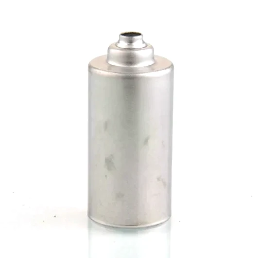
| Item | Brass Plain Sensor Sleeve Tube |
|---|---|
| Brand | AUNOV |
| Designing | Made to your 2D/3D drawings – non-standard features are feasibility-checked at quotation stage. |
| Tooling | Our toolroom covers die design, wire-cut EDM and maintenance, so die cost stays transparent, and the die remains dedicated to your part. |
| Samples | Sample parts are measured and reported before submission, so the part is proven before it is made in volume, and production starts only after your written sign-off. |
| Materials | Carbon steel (SPCC / DC01), 304 / 316 stainless steel, aluminium and brass are held on site; the final grade is fixed with the drawing review. |
| Surface finish | Surface treatment matched to the duty: plating, coating or polishing; finish thickness and adhesion checked on the first article. |
| Processing | Blanking, drawing and piercing in sequence, then machining of sealing faces; every stage is logged against your part number. |
| Equipment | Hydraulic presses for drawing, with CNC turning for finishing, with in-house toolmaking to keep dies and fixtures maintained. |
| Tolerance | +/-0.03 mm on stepped bores, concentricity per print; GD&T per drawing, PPAP-style reports on request. |
| Delivery terms | FOB, CIF or DDP per Incoterms – payment by T/T or L/C, with shipping quoted door-to-door. |
Related Products


Frequently Asked Questions
What makes an automotive coolant temperature sensor harder than it looks?
The problem is not the temperature. The sensor has to be thermally correct, sealed against coolant, mechanically robust to a vibration environment, and electrically connected, and all four compete for the same thin wall. A change that improves one of those usually harms another, so the design is a set of managed trade-offs rather than a single optimum.
Why does the coolant chemistry decide the material?
Most modern coolants are glycol-based and acidic, so an acidic glycol coolant quietly removes brass from the shortlist on most engines. Almost nobody states the coolant on the sensor drawing, so this is a question to ask at enquiry rather than assume. The wall then has to be right for sealing, vibration and response all at once.
How do you get a fast response when the wall cannot be made thinner?
Where a genuinely fast response is needed and the wall must stay thick for strength, the answer is a thermally conductive insert or a filled thermowell rather than a thinner steel. Blanking, drawing and piercing run in sequence, then sealing faces are machined at +/-0.03 mm on stepped bores with concentricity per print. This keeps the mechanical wall while shortening the thermal path.
What are the two leaks a sealed coolant sensor has to manage?
A sealed sensor with no vent path will either leak or drift, and it is better engineering to specify which happens than to leave it to whichever seal is weakest. A sealed unit also needs a mounting face that acts as a thermal couple to stay unmasked. Vibration loads the drawn corner repeatedly, so that corner is the fatigue-prone detail.
Request a Quote for This Part
Send a drawing or sketch — get material advice, tooling cost and a per-piece price within 24 hours (working days).