
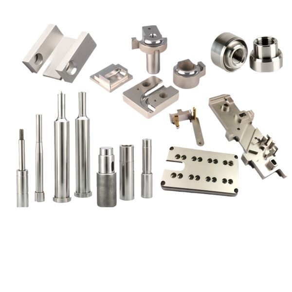
Plate flatness over the full area is more important than thickness uniformity for most mounting applications
A machined plate—whether it is a base plate, an adapter plate, a spacer, or a mounting bracket—is most commonly judged by its flatness when bolted to a reference surface. A plate that measures 10.00 ±0.05 mm thick everywhere but has 0.08 mm of bow across its 100 × 100 mm face will create a gap when bolted at its four corners; the fastener preload will bend the plate closed, introducing bending stress that did not exist in the design calculation and potentially distorting any features (bores, slots, or threaded holes) that were machined assuming the plate would be stress-free in service.
We machine plate faces to 0.02 mm flatness over the full area as a default specification unless the drawing calls out something looser. This is achieved by a facing operation with a large-diameter face mill (50–80 mm for plates up to 150 mm wide) taking a light final pass at 0.1 mm depth of cut. The key to consistent flatness is controlling thermal expansion during the cut: we allow the machine to warm up for 15 minutes before starting critical facing operations, and we use coolant (flood or mist) to keep the workpiece temperature stable within ±5 °C during the pass. Plates that still exceed 0.02 mm after initial machining receive a surface grinding pass (reciprocating grinder, 0.01 mm stock removal) which reliably achieves 0.005 mm flatness.
Pin press-fit tolerance determines whether the assembly is permanent or serviceable
A machined pin—dowel pin, locating pin, pivot pin, or shoulder pin—fits into a bore with either a clearance fit (removable, for serviceable assemblies) or an interference fit (permanent or semi-permanent). The choice of fit class affects not only the assembly force but also the long-term behavior of the joint under vibration and thermal cycling.
For a standard 8 mm dowel pin in a 316 stainless steel plate:
- Clearance fit (H7/g6): Bore 8 +0.015/0, Pin 8 -0.005/-0.014. Clearance 0.005–0.029 mm. Assembly by hand or light press. Removable without damage. Suitable for locating pins that are removed during maintenance.
- Transition fit (H7/k6): Bore 8 +0.015/0, Pin 8 +0.010/+0.001. Interference 0–0.014 mm or slight clearance. Assembly by light arbor press (500–2000 N force). Removable with effort; may mark the bore slightly on disassembly. Suitable for pins that should stay in place during normal operation but be replaceable if damaged.
- Interference fit (H7/p6): Bore 8 +0.015/0, Pin 8 +0.024/+0.015. Interference 0.009–0.024 mm. Assembly by hydraulic or thermal press (2000–10000 N force). Effectively permanent; removal requires heating the plate or damaging the bore. Suitable for structural pins that must never come loose under vibration.
We verify pin fits using class-specific go/no-go ring gauges on the pin diameter and plug gauges on the bore, plus a sample assembly test on the first article that measures the actual insertion force with a load cell.
Punch component edge quality after blanking depends on the die clearance and material condition
When “assorted CNC machined parts” includes punch components (blanks, washers, shims, or flat springs produced by stamping rather than machining), the edge quality of the punched part is determined by the die clearance (the gap between the punch and die edges, typically expressed as a percentage of material thickness) and the material’s ductility.
The optimal clearance for most stainless steels is 5–10 % of material thickness per side. Below 5 %, the punch shears the material with minimal plastic deformation, producing a clean edge with a small fracture zone (roughly 10–15 % of the thickness) but at the cost of very high punching force (which shortens die life). Above 15 %, the material stretches and tears rather than shears, producing a large fracture zone (40–60 % of thickness) with a rough, irregular edge and significant rollover (bending of the material edge outward).
For our punch components in 304 and 316 stainless steel with thicknesses of 0.5–3 mm, we target 7–8 % clearance per side and inspect the edge quality at 20× magnification on the first article and at SPC intervals thereafter. The acceptance criterion is: fracture zone < 25 % of thickness, burr height < 0.05 mm, and no visible die marks (scratches or galling) on the punched face. Parts exceeding the burr height limit go through a secondary deburring operation (vibratory tumbling or brush deburring); parts with excessive fracture zone trigger a die sharpening or replacement before the next run.
Threaded hole depth in thin plates must account for the effective engagement length
When a plate thinner than 6 mm receives a tapped hole, the effective thread engagement length may be significantly less than the tapped depth because the drill point (typically 118° included angle) creates a conical bottom that contributes few usable threads. For a 4 mm thick plate tapped M3×0.5 to a depth of 3.5 mm, the conical bottom occupies roughly 0.8 mm of that depth, leaving only 2.7 mm of full-thread engagement—about 5.4 threads at 0.5 mm pitch. If the mating fastener is a socket head cap screw with a body bore (unthreaded shank) that extends into the tapped hole, the effective engagement drops further to perhaps 3–4 threads, which may be insufficient for loads above 1000 N in aluminum or 3000 N in steel.
We calculate the minimum required thread engagement using the formula L_e = 2 × D + 6 × P (where D is the nominal diameter and P is the pitch), which for M3 gives L_e = 2×3 + 6×0.5 = 9 mm—far more than a 4 mm plate can provide. When the drawing calls out a threaded hole in a thin plate and the calculated engagement is insufficient, we add one of the following features (in order of preference): (a) increase the local plate thickness with a boss or spot-face, (b) install a helicoil or thread-insert to provide full-depth steel threads in a thin aluminum plate, or (c) use a through-bolt with a nut on the back side instead of a tapped hole. We document the chosen solution on the first-article traveler and confirm it with the customer before production.
Surface treatment selection for plates and pins depends on the environment and the function
“Assorted CNC machined parts” covers a range of surface treatment requirements from bare-machined (for internal components) to decorative anodize (for external appearance). The selection matrix we use:
- Bare / passivated: Internal structural plates, spacers, and pins in dry, indoor environments. 316 stainless steel: passivate per ASTM A967 (nitric or citric acid). Carbon steel: apply rust preventive oil. Cost: negligible.
- Zinc plating: Carbon steel plates and pins in general industrial environments (indoor, non-corrosive). Provides 72–500 hours salt spray protection depending on chromate type (clear = 72 h, yellow = 200 h, black-roasted = 500 h). Cost: ~0.03 USD/cm².
- Nickel plating: Wear-resistant surfaces on pins and bushings. Hardness 500–800 HV. Good corrosion resistance with a chrome topcoat. Used for pivot pins and wear plates. Cost: ~0.08 USD/cm².
- Type II anodize: Aluminum plates and enclosures. Natural (clear), black, or colored. Thickness 10–15 µm. Provides corrosion protection and decorative finish simultaneously. Cost: ~0.05 USD/cm² including masking if needed.
- Electroless nickel: Complex geometries (internal bores, deep recesses) where electroplating would produce uneven thickness. Uniform deposition regardless of shape. Hardness 500–700 HV as-plated; can be heat-treated to 900+ HV. Used for precision bushings and wear plates with internal bores. Cost: ~0.12 USD/cm².
We apply the surface treatment specified on the customer drawing. If the drawing is silent, we apply the minimum treatment necessary to prevent corrosion during shipping and storage (passivation for stainless steel, oil for carbon steel, no treatment for aluminum) and note the as-shipped condition on the CoC.
How we handle mixed-geometry orders where plates, pins, and punch components are combined in one PO
A single purchase order for “assorted CNC machined parts” often contains a mix of geometries: some parts are turned (pins, bushings, shafts), some are milled (plates, brackets, housings), and some are stamped (washers, shims, clips). Each geometry type requires different machines, different fixtures, and different inspection methods. Our approach is to split the PO into sub-lots by manufacturing process, route each sub-lot through the appropriate work cell, and then consolidate all sub-lots into a single shipment with a consolidated packing list and Certificate of Conformance.
The consolidation step includes:
- Visual segregation check: Verify that each part matches its drawing (correct geometry, correct finish, correct quantity). Mixed-geometry orders have a higher risk of part mix-up because similar-looking parts (e.g., a 20 mm OD washer vs. a 20 mm OD spacer) may belong to different line items.
- Individual packaging: Each line item is bagged separately with a label showing the part number, quantity, and PO reference. This allows the customer to receive-inspect by line item without opening every bag.
- Consolidated CoC: One certificate that lists all line items with their respective material certs, dimensional data, and surface treatment verification. The customer files one document instead of one per part number.
This consolidation process adds approximately 0.5 minutes of labor per line item but eliminates the #1 customer complaint for assorted-parts orders: “wrong part in the bag” or “missing part that was on the packing list.”
Our CNC Machining Parts range is where this part sits. The cnc machining parts pages carry the process notes, common materials and inspection points behind every product in the family.
Specifications
| Item | Assorted CNC Machined Plates Pins and Punch Components |
|---|---|
| Brand | AUNOV |
| Designing | Share your print, or send a part to be measured, DFM feedback is returned with the quote. |
| Tooling | Every die designed and built in our toolroom, held and maintained under your part number. |
| Samples | First-off samples are sent with a dimensional report and material certification. |
| Materials | Stock covers carbon steel (SPCC / DC01), 304 / 316 stainless steel, aluminium, brass and copper, per the drawing. |
| Surface finish | Plating, e-coat, powder coating, anodising or passivation as the drawing calls out, selected against the drawing requirement. |
| Processing | Stages of deep drawing, annealed in line where the draw ratio calls for it, then pierced and CNC-machined under our own roof. |
| Equipment | 5-250 T mechanical presses plus 250-500 T hydraulic presses, in-house CNC cells and a temperature-controlled inspection room. |
| Tolerance | Tolerances to +/-0.1 mm as drawn, with machined features to +/-0.03 mm. |
| Delivery terms | FOB standard, DDP offered for EU and US, T/T and L/C; D/P on repeat accounts, call-off schedules supported. |
Related Products


Request a Quote for This Part
Send a drawing or sketch — get material advice, tooling cost and a per-piece price within 24 hours (working days).